The Art of Slitting
To fully grasp the cutting edge technology used in the slitting/shearing process is to understand the fracture mechanics of material.
Posted: October 2, 2008
When slitting or shearing material, many factors must be taken into consideration in order to produce a quality slit or sheared edge. Horizontal knife clearance, depth of penetration, size of the stripper rings, material characteristics, as well as the slitting head or shear itself will all enter into the equation. To properly manage all of these variables on a day-to-day basis under the pressures of meeting a production schedule truly makes slitting an art. To fully understand the slitting/shearing process is to understand fracture mechanics. Slitting is not simply a function of shearing the material in two. Shearing is only part of the story. In order to actually cut the material, sufficient compressive forces must be applied to cause it to fracture. When done correctly, you can produce a high quality cut with little or no burr.
FOUR COMPONENTS OF THE SLITTING PROCESS
The process of slitting is actually comprised of four separate and distinct components. The first two components of the process are rollover and burnish. The rollover is the initial step when the knives come in contact with the material. The knife contact area deforms the material, which in turn creates the rollover. Secondly, a portion of the edge is burnished, which is sometimes referred to as the shear zone. When looking at the edge of the strip, this is the shiny area.
When the compressive forces exceed the material’s ultimate tensile strength, a fracture takes place. The fracture zone is normally the largest zone within the slitting process. Not only is it the largest zone within the slitting process, it is also largely out of your control. Materials typically fracture at 7 deg to 9 deg depending on the type of material being slit, whether your knives align with the fracture plane or not. Consequently, the fracture will not go to your slitter knives — your slitter knives must go to or line up with the fracture.
When performed correctly, the slit edge will have a shiny shear zone, a darker fracture zone, and a defined straight line separating the two. The fourth component of the slitting process is the burr. This is the telltale sign of whether your set up is correct. Burr occurs in large part due to compressive displacement of the material and will form on the opposite edge of the rollover. The greater the compressive forces required to fracture the material due to a poor slitter knife set up, the greater the burr. If your slitter knife set up is correct and you have sharp knives, the burr will be minimal. This is due to the fact that the forces applied to the material to cause it to fracture have been kept to a minimum.
For many years, it was believed that dull knives alone caused excessive burr. However, today we know this is just one of a number of issues which can cause excessive edge burr. A good slitter or shear operator learns how to “read the edge.” Knowing how to discern what you see when you look at a slit or sheared edge can tell you if your set up is correct and, if not, what steps to take to correct the problem.
TOO LITTLE CLEARANCE
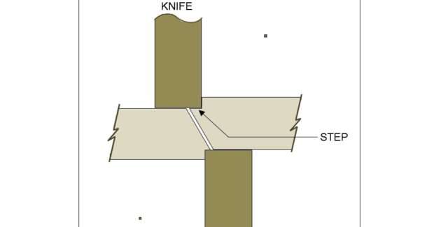
One of the most common set up mistakes is setting the knives with less than ideal horizontal clearances. Tight horizontal clearances misalign the knife edge with the fracture plane and create a step under the outside face of the knife. If your knives are sharp, they will cut this step off intermittently. The step that is cut off is a sliver and often looks like a piece of wire. These slivers will tend to accumulate around the slitting head or under the shear. As the knives get dull, they will tend to smear the step against the slit or sheared edge.
When the clearances are set too tight, the slit edge will have a deeper than normal shear zone, a smaller than normal fracture zone, and a jagged non-defined line separating the two zones with a burr on the bottom edge. When the horizontal clearance is set too tight, the knives must also be over-penetrated to make the material fracture. As a result, your knives dull faster, and camber is frequently introduced into the strip.
VERY TIGHT CLEARANCE
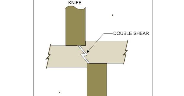
When slitting thicker materials and/or harder thin materials and your horizontal clearance is set too tight, you can actually get a double fracture. With this condition you have two fracture zones, each coming from the outside face of each knife. The fractures do not meet along a constant shear plane. Both fractures will travel toward the center of the material until they are close enough that the material breaks along its length and the two fractures meet. When you read the edge of a strip with this condition, you will see a shear zone which extends through most (and, in some places) all of the way through the thickness of the material. In order to separate the strips, it requires substantial over-penetration of the knives.
Consequently, you will have little or no fracture zone. When this occurs, the entire face of a slit coil may appear shiny. You will also have a heavy burr. This condition is very hard on your slitting head and tooling and will frequently lead to chipped or damaged knives. In addition, behind each shear zone there is a fracture. If the edge of the material is worked or welded, there is the possibility that the fracture will propagate further and the part produced can fail.
The harder the material, the less cutting required before the material fractures. The softer the material, the deeper the cut before the metal breaks. Harder materials require more horizontal clearance. Softer materials require much less.
TOO MUCH CLEARANCE
When the horizontal clearance is set too wide, there is again misalignment of the fracture plane and knife edge. Instead of shearing the material, you are literally tearing it in two. When you read the edge of strip with this condition, you will see a very heavy rollover above a very small to non-existent shear zone. The fracture zone will be almost the full thickness of the material, and you will have a very heavy burr. This condition also tends to chip the knives as it puts significant load on the edge of the blades.
VERTICAL CLEARANCE (PENETRATION)
When slitting, there is a direct correlation between the horizontal clearance and vertical clearance (depth of penetration) of the slitting knives. As a general rule of thumb, the harder the material, the less cutting that is required before the material fractures; the softer the material, the deeper the cut before the metal breaks.
Consequently, harder materials require more horizontal clearance, while softer materials require significantly less. An easy way to keep this idea straight is to think of a piece of glass. To cut glass, you need to barely scratch or scribe its surface. Once scribed, it can be fractured at this point. This would be the case with materials that are hard with high tensile strengths. While it’s necessary to cut high strength metal deeper than a piece of glass, proportionately the knife penetration is minimal relative to the fracture length that results. The greater the fracture length, the more horizontal clearance required to maintain proper alignment of the shear plane.
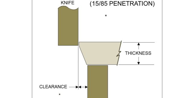
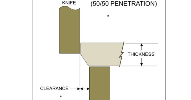
To the contrary, if you were to cut a piece of soft putty, it would be necessary to cut it through its entire thickness. Again, while most soft materials will fracture long before the knives will cut 100 percent of the material’s thickness, the amount the knives penetrate is much higher relative to the fracture length that occurs. When less fracturing occurs, less horizontal clearance is required to maintain the proper shear plane. The illustrations demonstrate the point. All the examples shown are for the same thickness of material but different tensile strengths. For relatively soft material, the knife penetration is relatively high. Consequently, the horizontal knife clearance is small as it relates to the percentage of material thickness. On soft “0” temper aluminum, you may have as much as a 50 percent knife penetration and a 50 percent fracture.
Consequently, the correct horizontal clearance would be approximately 5 percent to 7 percent of the material’s thickness. For mild steel, the typical knife penetration is 25 percent to 30 percent of the material’s thickness and the horizontal clearances would be set at approximately 10 percent. For material such as stainless steel and many of the higher strength low alloy steels, it may require as little as 5 percent to 10 percent penetration, with up to a 90 percent to 95 percent fracture. If this were the case, the horizontal clearance is frequently set at 20 percent or more of the material thickness.
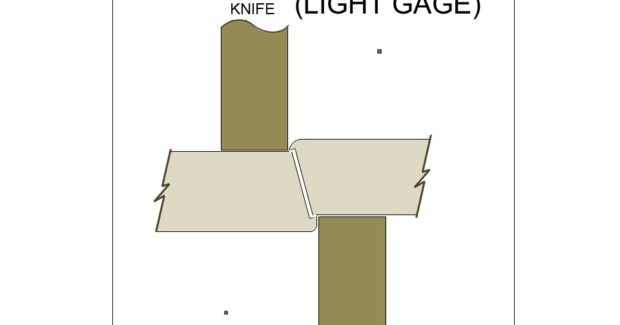
The tooling itself is also a major consideration. Knife companies, as well as their customers, have searched in vain for the perfect tool steel that fits all cutting applications. However, no one yet has found it. There is a trade-off between wear resistance and shock resistance. Wear resistant tooling lasts the longest, but is not very tough. Their use is typically limited to light gage applications. Shock resistant tooling is required for higher strength, thicker material but lacks long life. Consequently, it is important that the machine builder and end user work in concert with the tooling supplier to find the best balance for a particular application with the least amount of sacrifice.
While the above horizontal knife clearances are meant as a general guideline, in some instances it might be necessary to experiment with different types of knives and clearance to determine what results in the best cut and longest knife life. As you can see, there is a lot more that can cause a poor quality slit or sheared edge than simply dull knives. Understanding the direct correlation between horizontal and vertical knife clearance can help eliminate many of these problems. Knowing how to read the slit or sheared edge of your material can be your greatest asset. The finished cut edge can tell you what your problem is as well as how to fix it. Understanding fracture mechanics is truly the art of slitting.
Red Bud Industries, 200 B&E Industrial Drive, Red Bud, IL 62278-2198, 618-282-3801, Fax: 618-282-6718, www.redbudindustries.com.
Subscribe to learn the latest in manufacturing.

