State of the Art: CNC Plasma Cutting Software
Buyer’s Choice: A better understanding of the necessary software required for the newest highly productive CNC plasma machines separates the investment of a hands-on, low volume shop from one with high volume, repeatable parts. Here are the reasons why.
Posted: March 7, 2012
Software that is used in the CNC plasma cutting industry creates varying levels of confusion. Often, when speaking to a large group of potential CNC plasma cutting types, I can sense that look of frustration on many faces – that same frustration that I had back in the advanced math class I took in high school . . . when I did not understand the concept that the teacher was laying out on the blackboard, yet I did not want to raise my hand, an act that I just knew would tip off the rest of my classmates as to my lack of math skill!
While even the simplest versions of the software used for drawing, processing, nesting and creating torch motion in today’s CNC plasma systems are extremely complex, I would like you readers (especially those getting that glazed look) to have a little better understanding of the necessary software required for modern, highly productive CNC plasma machines.
So, let’s take a look at (1) the three types of software that are required on most of the new CNC plasma systems, (2) what the primary functions are of each, and (3) what advancements in this software can do for your performance and productivity on the shop floor.
BASIC SOFTWARE PACKAGES ON AN INDUSTRIAL CNC PLASMA SYSTEM
CAD (computer-assisted design) is available with different levels of complexity that fit many budgets. CAD drawing packages of simple or older technology can be found as downloadable files online for free, can be purchased at relatively low prices at the local computer software store, or you can spend thousands of dollars for CAD software specifically designed for industrial design use.
The differences in these packages are generally based on the complexity of the program: 2D or 3D drawings, the ability to rotate and view the drawing, the ability to calculate material sizes and strengths and load capacities. CAD helps with detailing, drawing and engineering the product design configuration. For the majority of flat plate and sheet cutting applications with plasma cutting, CAD is simply used to draw a detailed, dimensioned drawing of the part that needs to be cut.
Often, if there are multiple processes that need to be applied on the CNC cutting machine, such as marking (for layout lines or alpha-numeric pat numbers) then cutting of the internal and external contours, the CAD drawing will be separated into “layers” that represent one drawing for the marking process and a second drawing for cutting, but both drawings/layers are included in one file.
Simplified further: CAD is the software used by a draftsman, designer, or programmer to draw the actual part that needs to be cut from the correct thickness and type of material. The most common output of a CAD program for use with plasma cutting will be a .dxf file. This is a typical AutoCAD file format that is used by many CAD drawing file developers, such as AutoCAD or SolidWorks.
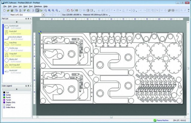
CAM (computer-assisted manufacturing) is commonly known on plasma cutting machines as “post processing” or “nesting” software. Though generally not available in the office supply store, this software is available in many different versions, prices and levels of complexity. In its simplest form for plasma cutting, this software takes the .dxf file (or part drawing) and applies some necessary modifications that must be done before the part can be cut with a plasma torch.
First, the CAM software needs some inputs from the user that indicates the width (kerf) of the cut that will be done. This requires an expert that knows plasma cutting to input a dimension for the particular plate thickness, the plasma power level, and the cutting speed and torch height – all of these parameters can affect cut kerf – so that the software can offset the cut and allow the part to be cut with the correct dimension.
Second, the software must determine where to locate starting points for piercing the plate in scrap material so that the outside contour of the cut is not distorted from piercing. Then, again using expert operator input, lead ins and lead outs are applied to the part drawing to lead from the pierce point to the actual contour of the part.
The software also determines when the plasma torch should start, when it should stop, when the motion of the torch should start and stop and at what speeds the torch should be cutting – again, all inputs from an expert operator. The operator generally gets the data (lead in length, kerf width, cut speeds, etc.) from the plasma system operator’s manual, as well as from experience with similar cutting jobs.
Simplified further: The operator inputs knowledge and data required, The software also reads the dimensional information from the CAD drawing file, then the CAM software “processes” this data and develops a list of code called “machine code”….which is a road map for the CNC control that tells it what speed, when to move, what direction, when to activate the plasma and the height control. This software also often has “Nesting” capability…..which means the operator can tell it to cut multiple parts, and the parts (with more input data) can be aligned on the plate for best plate utilization. Typical CAM software suppliers specific to plasma cutting would be MTC or SigmaNest.
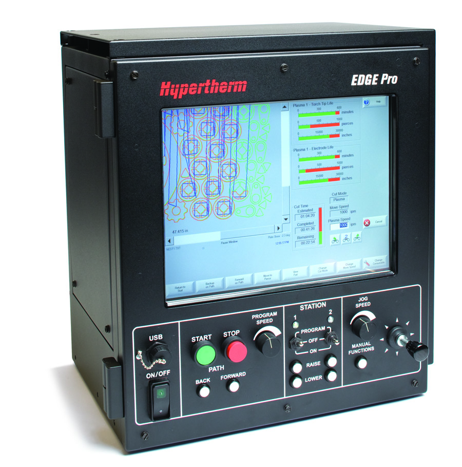
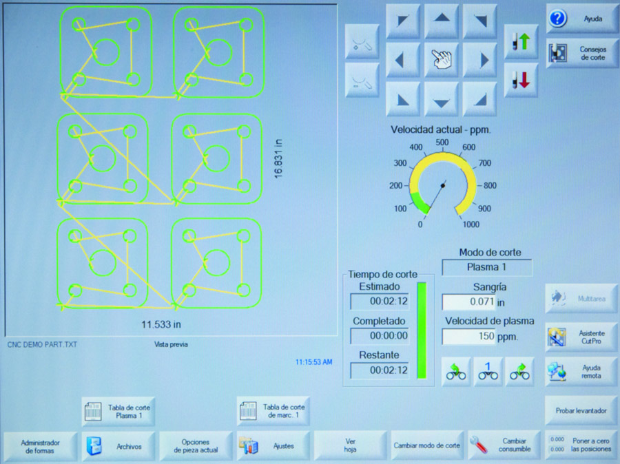
CNC (computer numerical control) operating software is integrated into the control on plasma cutting machines and is generally proprietary to a specific brand of controller. For example, the Hypertherm controls use software called “Phoenix” that has been developed, modified and improved over the years. This operating software is fairly complex, as its primary function is to receive the “machine code” from the CAM (or post processor or nesting software) and interpret the code, converting it into properly timed electrical signals that drive the X-axis, Y-axis and Z-axis motors for machine motion.
CNC software also converts the code into properly time electrical signals to activate and deactivate the plasma, the torch height control, the marking process and any other peripheral device. This software also accepts input from the expert cutting machine operator in regards to cut speed, cut height, pierce height, amperage, voltage to produce the best quality cut possible.
Simplified further: This software is proprietary and cannot be purchased separately because it is developed specifically to control the operating functions on a CNC machine, yet it reads the machine code and interprets it, combines it with operator inputs (referred to as a human machine interface) and then directs all electromechanical components of the machine to function in a well-choreographed cutting process.


