CO2 vs. Fiber-Laser Technology: Which One Is Right for You?
A careful and comprehensive analysis must examine not only the cutting equipment itself, but also the impact the new equipment will have on other existing fabrication processes.
Posted: March 5, 2013
Over a relatively short period of time we have seen exponential advances in fiber laser technology used for flat sheet metal cutting. In just five years, fiber lasers have achieved the 4 kW cutting threshold that it took CO2 lasers approximately four times as long to reach.
http://youtu.be/a5JMrAJqxjc
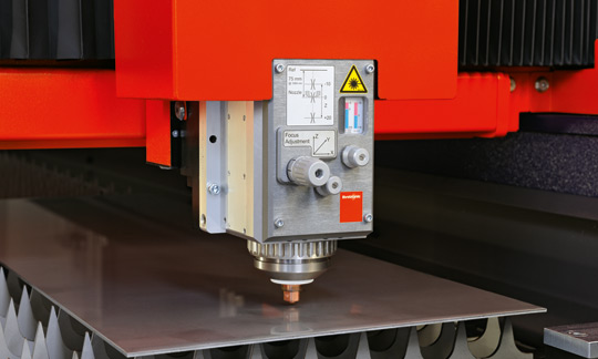
The Bysprint fiber, equipped with an undemanding high-tech fiber laser, stands for unprecedented parts output, especially in the thin sheet metal range up to four millimeters, trouble-free operation, high energy efficiency and high material flexibility.
In all fairness, fiber lasers – some exceeding 20 kW – have been used by other industries for many years in applications other than sheet metal cutting.
The primary advantages of cutting flat sheet metal with this laser technology are derived from its monolithic, fiber-to-fiber, compact solid state design configuration that is maintenance free and provides a lower cost of operation than can be achieved with comparable CO2 lasers.
The focused beam of even a 2 kW fiber laser demonstrates a 5X greater power density at the focal point when compared with a 4 kW CO2 laser. It also possesses a 2.5X greater absorption characteristic due to the shorter wavelength of the fiber laser (see Figure 1 and Figure 2).
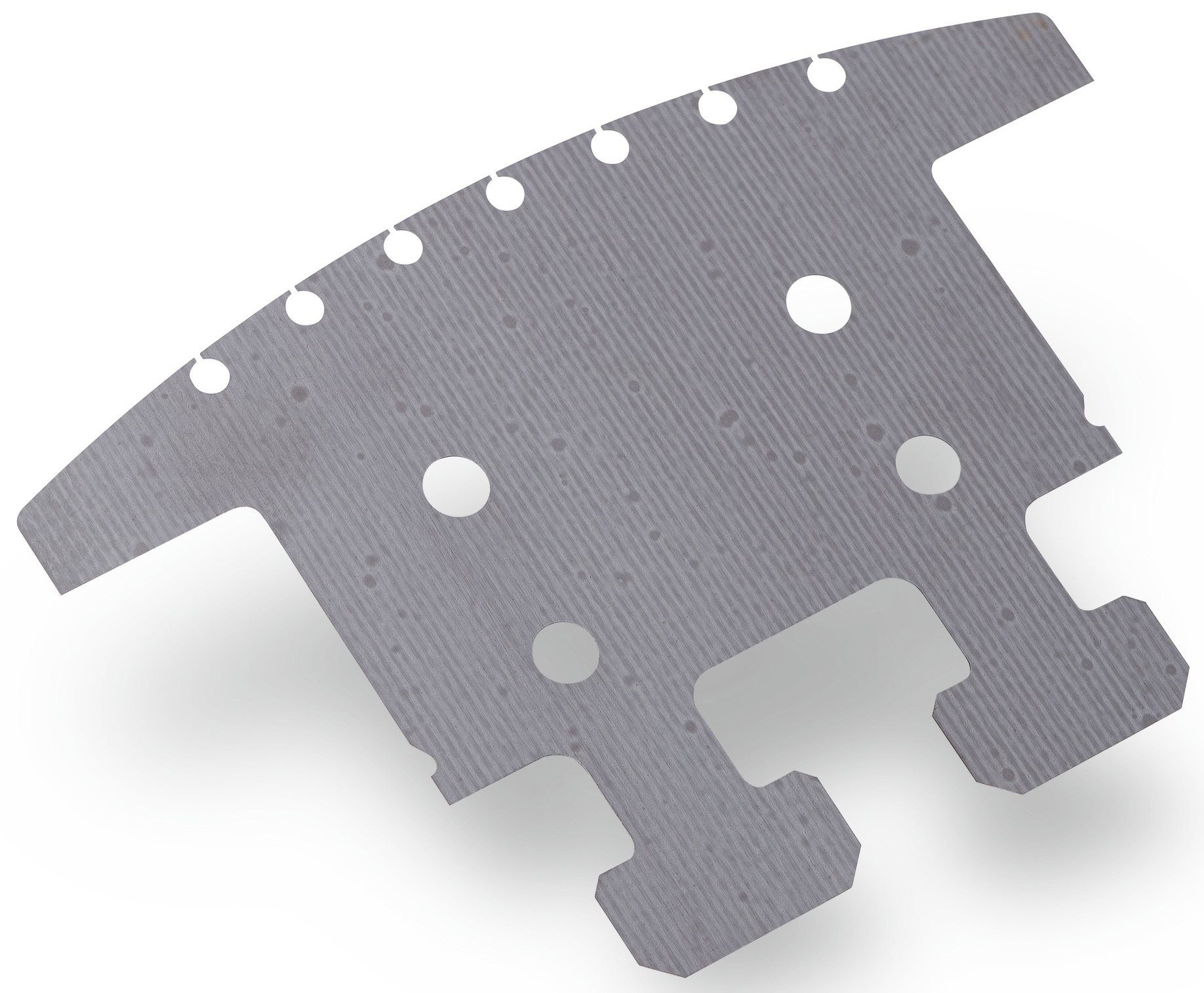
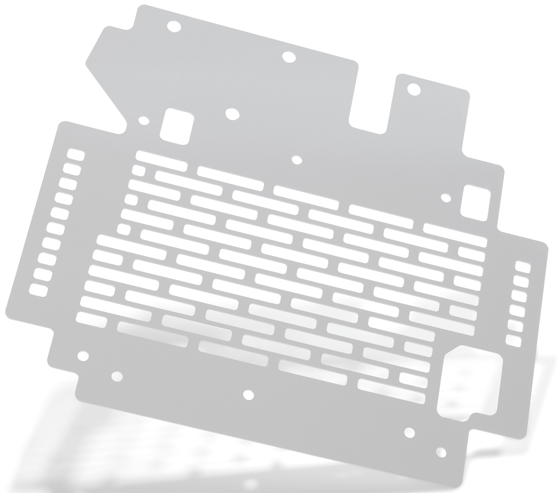
The higher absorption of the fiber wavelength and the higher power density created by the focused beam combine to achieve a 300 percent increase in cutting speed in thin materials that are less than 1/8 in thick. Systems can certainly cut thicker and faster with higher fiber laser power, but the “sweet spot” where the most valuable benefits are realized remains in the 1/8 in and under range when making comparisons with CO2 systems.
These benefits are most profound when nitrogen is employed as an assist gas because the molten material is expelled from the kerf by the nitrogen just as fast as it can be brought to a molten state. Compressed air may also be used in this manner, being that it is primarily comprised of nitrogen.
Research shows that approximately 70 percent of all cutting applications in the flat sheet cutting market are in the thin-material range under ¼ in thick. This constitutes a large portion of the market segment for flat sheet cutting and thus represents significant market potential.
Nonetheless, CO2 lasers are still the most widely used and broadly sold cutting systems on the market today. Their reputation has been built over many years and, while the earlier mentioned leaps in process technology have benefitted fiber lasers, there have also been important enhancements in CO2 laser cutting systems as well.
Though wattage levels for CO2 lasers have leveled off for the most part at 6 kW, other advances in new resonators have made CO2 lasers more economical to operate and enable them to process faster.
For example, high voltage and RF power supplies now used in CO2 resonators have evolved from vacuum tubes to solid-state devices and gas turbines have exchanged hard-bearing contact for non-contact magnetic bearings. These advances caused the related maintenance aspects of CO2 resonators to largely disappear and now be considered essentially maintenance free.
New CO2 resonators are also able to shift into power-saving modes that reduce energy consumption by as much as 80 percent when idling. And rapid-piercing technologies can significantly reduce – by up to 80 percent – the time needed to pierce through materials, then monitor when the pierce is completed to immediately start the cutting process.
The latest CO2 resonators also employ automatic power monitoring and optic monitoring safeguards that are especially important to ensuring cut quality is maintained when running an automated, lightly manned operation. If a problem is detected in the optics, the monitoring system will automatically stop the cutting process to prevent further deterioration of the optics.
Since CO2 and fiber laser systems have both benefitted from these types of technological advances, the real question that remains is this: Which one is right for your application?
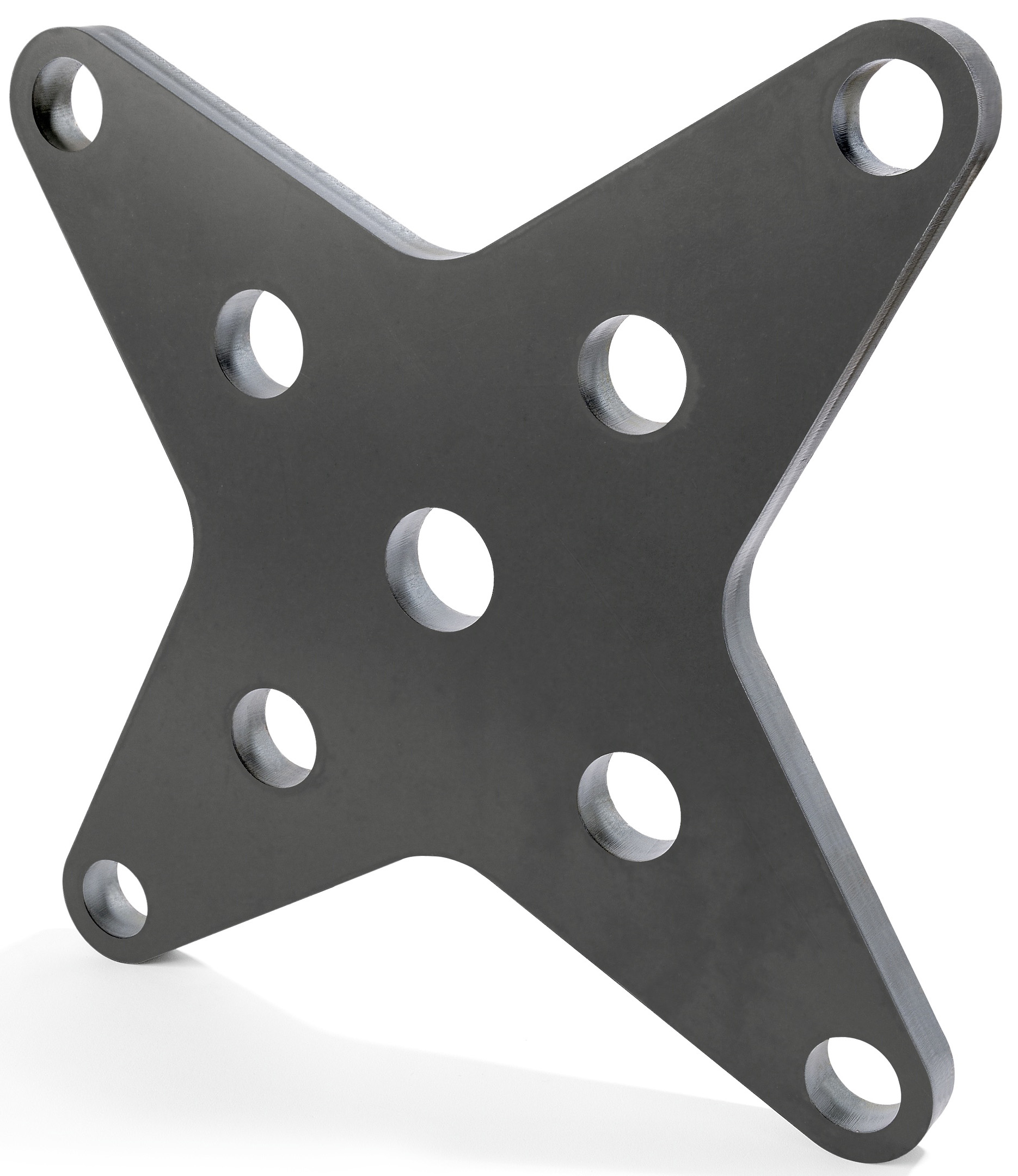
Traditional job shops must maintain flexibility so that they can process a full range of material thickness at competitive rates. While fiber lasers will certainly outperform CO2 in the thin material range below 1/8 in thick, CO2 lasers will outperform fiber in the thicker material ranges above ¼ in.
Fiber can cut copper, brass and aluminum much better and more safely than CO2 because the beam is more readily absorbed and not reflected. Fiber laser operating costs are typically half of what a CO2 system can offer due to the lower electrical consumption and high electrical efficiency of fiber lasers. Other factors that favor fiber lasers include the absence of mirrors or beam path bellows that are necessary in CO2 systems.
The question of which technology is best really boils down to your operation. How well does the system fit your particular application? How much faster and how much more cost effective are your parts going to be produced? It is necessary to make a careful analysis of all of the pertinent data, including the application range, operating costs, throughput, cost of ownership and, of course, the investment costs.
The other key aspect in determining which technology to choose from is differentiation. How important is it to distinguish your operation from that of your competition? Will a high speed 6 kW CO2 laser with a larger table size provide a significant competitive advantage, or will a fiber laser give you a better competitive advantage?
Whatever the final conclusion, don’t forget about the impact of this investment on your downstream processes: What effect does adding this new laser cutting system have on the flow of operations performed on the parts after they are cut?
For example, will cash be hoarded by an in-process inventory bottleneck created at the press brake because the laser now cuts more parts per hour than the brake can form? In other words, are you investing in the level of downstream automation that will be needed to maintain pace with the new, shorter cycle times and keep your shop flow balanced?
A careful and comprehensive analysis must examine not only the cutting equipment itself, but also the impact the new equipment will have on other existing fabrication processes.

