Beyond the Punch: Giving Thought to Tooling
By taking time to review old processes, tooling libraries and programming methods, a shop can implement simple tooling changes that positively impact production, minimize costs, reduce space or downtime, and maximize the return.
Posted: May 13, 2013
When a company invests in a new punching or punch-laser combination machine, there are expectations on how the new technology will increase productivity. However, once the research is done and the machine is purchased, there is more to consider.
http://youtu.be/vHlp7N79vPU
Many fabricators ignore the opportunity to critique how their established ways of manufacturing will match the capabilities of the new machine. Often overlooked, the plant misses out on the full potential of the technology and is never the wiser. By taking time to review old processes, tooling libraries and programming methods, a shop can implement simple tooling changes to positively impact production, minimize costs, reduce space or downtime, and maximize the return.
REDEFINE DIE CLEARANCE
We begin by assessing die clearance needed for proper shear as the material is punched. Existing standards may no longer be optimized for the current materials or processing capabilities. Therefore, it is important to redefine die standards to match the current processing capabilities and potentially reduce the tooling library.
First, list all materials processed and identify the primary ones. The rigidity of the tool holding on a new machine and the centricity of the punch and die should allow greater flexibility in die clearance. To ensure maximum tool life, we recommend maintaining a gap range between 10 percent to 25 percent of the material thickness (Figure 1).
Calculate the optimal die clearance for your selection of primary materials. It is best to round to the nearest .004 in increment to help standardize the new tool library. After calculating the range for each of your primary materials, the gaps should be clear. Consider these and your secondary materials to determine which additional sizes you need to complete your tooling library.
RETHINK THE TOOLING LIBRARY
Once the die clearances are defined, you can begin to rethink the standard tools you need in your library. Since the tool library develops over time, it may contain an excessive range of tool lengths for the same tool width. Especially if the shop was running older equipment, bad tool alignment and poor tool rigidity would have required additional tool lengths.
In addition, previous programming rules for nibbling or stepping may have limited the overlaps to at least one-half of the tool’s length. As a shop moves to more modern punching machines, new developments such as “hydrostatic bearings” will easily allow for overlaps as low as one-half of the material thickness. Simply put, more work is achieved with fewer tooling sizes.
For example, a company might own eleven rectangular tools all .125 in wide (Figure 2) yet the new punching machine allows tool lengths to be increased in larger increments. The shop is now able to achieve the same range of results with only four tools instead of eleven. Review all the current standard tools: circles, squares, rectangles and oblongs, and consolidate based on current needs and future expectations.
Once the standard tools are established, address your specially designed tools. Often, the original designs are less practical, oversized or limited in flexibility due to machine technology developments. The best way to identify improvement opportunities for special shapes is to work closely with your OEM tool supplier.
Implementing tool rotation, for example, may reduce scrap and increase flexibility. To illustrate this point, let’s consider the tool shown in Figure 3. The original design was developed for an older machine without tool rotation. The large tool with single corners demands wide spacing between parts and along the border. A substantial amount of the material is wasted. By using the tool rotation technology available on a new high-quality punching machine, the design can be improved. The tool is now half the size and designed for a common edge. There is less scrap and runtime has been reduced.
Taking the redesign a step further, we can capture the full benefits of the tool rotation technology. Part and border scrap is further reduced and the flexibility of the tool has increased. The tool is also only a quarter of its original size. In addition, we were able to slightly adjust the design to accommodate larger arc lengths and ability to integrate micro-tabs.
REVIEW THE MANUFACTURING PROCESS
Once the tools are defined, review new nesting opportunities and advanced processing methods in an effort to increase part yield, reduce scrap and minimize handling cost. New developments, such as common edge nesting which punches two adjacent parts with a single hit of the tool, will eliminate the skeleton between the parts.
By combining nesting algorithms and innovative tool technology, skeleton free processing with up to 15 percent higher material utilization can be achieved. Active die technology lowers the die during positioning for scratch-free punching and forming and broadens the range of forming options. The technology on a new punch or combination machine will vary and it is essential that you understand what is possible before attempting to rethink the process.
RESEARCH NEW TOOLING TECHNOLOGIES
After reviewing your tooling needs and the manufacturing process, research new tooling developments. Roller technology increases processing speeds in forming and slitting operations. Deburring tools and the MultiBend tool eliminate a processing step, while new tapping tools form threads within a single punch cycle.
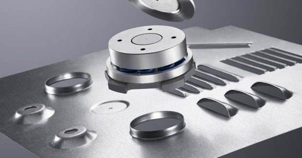
The MultiShear achieves the quality of laser-cut edges with a tool and die and a foil slitting tool can be especially useful when processing coated stainless steel. The MultiTool integrates up to ten different punches and dies into a single tool. Adaptive stroke technology determines the thickness of the sheet and precisely calibrates the ram stroke.
There are also new possibilities for scribing and high speed marking (dot matrices) on the punch or combination machine, such as the MultiTool and EasyType. Adding specialty tools might prove an easy way to increase productivity.
Finally, consider your tooling setup, maintenance and storage equipment. A fully automated sharpening system, such as QuickSharp, improves the regrinding process while a tool setting device insures alignment, measurement and accurate data output. Temporary tool storage, tool storage cabinets and more efficient ways of transporting tools may prove simple ways to reduce downtime and increase space.
Avoid the temptation to duplicate old processes, tooling libraries and programming methods. Work closely with the OEM tool supplier, review standards and solutions with your work plans involved to realize all the advantages the latest technology affords. It will prove well worth your time.


