Using Laser Beam Welding with Electron Beam Welding for Complex Geometry and Superior Metallurgy
Using both laser and electron beam technologies in a single facility can streamline the fusing of complex geometries that are required on parts such as sensors, medical devices, and products that require a sealed vacuum within the finished part.
Posted: September 27, 2013
Proponents of laser beam welding (LBW) and electron beam (EBW) welding each pronounce the singular praises of their favored technology, but in many cases the best solution for a customer is actually to use the technologies together.
This is especially true for fusing together complex geometries and meeting the demands for superior metallurgy. Using both laser and electron beam technologies in a single facility can streamline the manufacturing process when a component’s design incorporates both EBW and LBW welds. Examples include sensors, medical devices, and products that require a sealed vacuum within the finished part.
Usually, both technologies are needed either when the size of the final assembly is too large for an available EB welding chamber, some component in an assembly is incompatible with vacuum processing (such as a liquid), or when the weld is non critical and shallow, therefore not requiring a more potentially expensive EB weld.
LASER BEAM WELDING: SIMPLER TOOLING, SHORTER CYCLE TIMES
LBW uses either a continuous wave (CW) or pulsed beam of photons. With CW systems, power output is operated continuously over time. Pulsed systems are modulated to output a series of pulses. With both methods, the laser beam is optically focused on the workpiece surface to be welded.
It is the higher energy density of the laser that allows the surface of the material to be brought to its liquidus temperature more rapidly, allowing a shorter beam interaction. Energy is thus given less time to dissipate into the interior of the substrate. This results in a shallower heat-affected zone and less fatigue debit to the component. Beam energy can be tailored to produce desired pulse profiles.
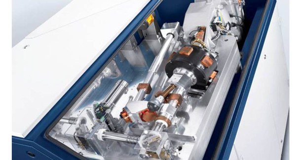
Weld seams may be produced by overlapping individual pulses, which tends to reduce heat input by the brief cooling cycle between pulses, an advantage for producing welds in heat sensitive materials. Figure 1 depicts the construction of a solid-state laser welding system.
Salay Stannard, a materials engineer at Joining Technologies (East Granby, CT), notes that CW lasers can achieve penetrations up to and exceeding 0.5 in, while pulsed lasers typically achieve only 0.030-0.045 in. She says, “These results may vary between laser systems and are largely dependent on processing parameter choice and joint design. Since the heat source in this type of welding process is the energy of light, the weld material’s reflectivity should be considered. For example, gold, silver, copper and aluminum require more intense energy input. Once melted, the reflectivity is reduced and the thermal conductance of the process progresses to achieve penetration.”
Due to this feature, LBW is sometimes referred to as a “purifying process.”
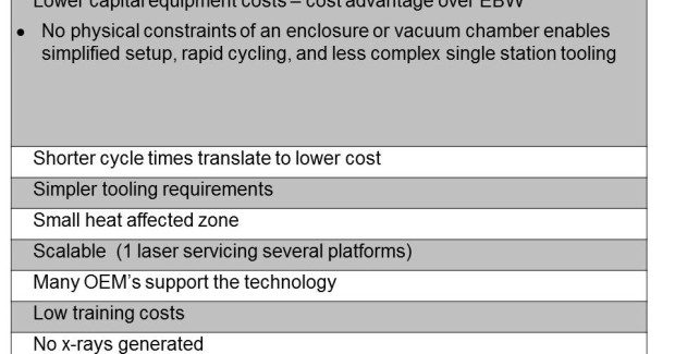
As noted, the laser’s high power density results in smaller heat-affected zones and ensures that critical components are unharmed. This has particular advantage for surgical instruments, electronic components, sensor assemblies and other precision devices. LBW does not generate any x-rays and is easily controlled with automation and robotics. Generally, LBW has simpler tooling requirements and there are no physical constraints of an enclosure or vacuum chamber. Shorter cycle times translate to cost advantages without sacrificing quality. Table 1 lists the advantages of continuous wave and pulse LBW.
ELECTRON BEAM WELDING ADVANTAGES: DEEPER PENETRATION, CONTAMINATION-FREE GUARANTEE
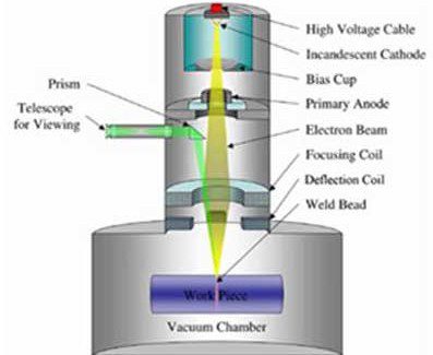
Widely accepted across many industries, EBW permits the welding of refractory and dissimilar metals that are otherwise unsuited for other methods. As shown on Figure 2, the workpiece is bombarded with a focused stream of electrons travelling at high speed. The kinetic energy of the electrons is converted to heat energy, which in turn is the driving force for fusion. No added filler material is required and distortion is minimal.
Ultrahigh energy density enables deep penetrations and high aspect ratios, while a vacuum environment ensures a contaminant free weld that is critical for metals such as titanium and nickel-based superalloys. However, the main advantage for operating under vacuum is to control the electron beam precisely. Scattering occurs when electrons interact with air molecules; by lowering the ambient pressure under vacuum electrons can be tightly controlled.
Modern vacuum chambers are equipped with state-of-the-art seals, vacuum sensors, and high performance pumping systems enabling rapid evacuation and increased processing time. This advantage makes it possible to focus the electron beam to diameters of 0.3 mm to 0.8 mm.
By incorporating the latest in microprocessor control (CNC) and systems monitoring for superior part manipulation, parts of various size and mass can be joined without excessive melting of smaller components. The precise control of both the diameter of the electron beam and the travel speed allows materials from 0.001 in to several inches thick to be fused together. These features make EBW an extremely reliable technology.
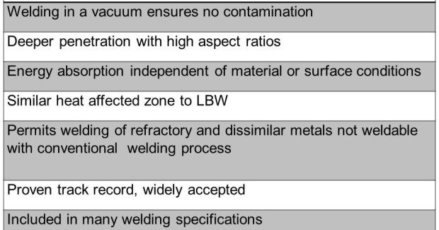
The process also puts a small amount of total heat into the workpiece being welded, which produces the smallest amount of distortion and allows finish machined components to be joined together without additional processing. Table 2 lists the main advantages of EB welding.
According to John Rugh, marketing and general sales manager for PTR-Precision Technologies, Inc.(Enfield CT), EBW is a process that will be in use for a long time. “Since most EB welding is performed inside a vacuum chamber, it is an excellent fit for joining advanced materials used in such industries as aerospace, power generation, medical and nuclear, which need to be produced in a vacuum environment to protect them from oxygen and nitrogen found in an open air environment.”
He adds, “The cleanliness of the welding environment is one variable that you just don’t have to worry about. In addition to providing the ideal welding environment, new EB welding controls allow for fast electromagnetic deflection of the beam, which allows the heat input of the weld and surrounding area to be customized for optimum material properties.”
For example, this rapid deflection allows preheating, welding and post heating simultaneously just by rapidly moving the beam location, focus and power levels. This provides the ability to weld difficult or “impossible to weld” alloys.
Another area where use of EBW is growing is in manufacturing turbochargers for diesel engines, which are growing in popularity due to their potential to increase energy efficiency. Turbochargers are required to pressurize the fuel air mixture going into the diesel engine.
Geoffrey Young, the general manager of Massachusetts-based Cambridge Vacuum Engineering, commented, “We are seeing many modern passenger car and commercial vehicle engines that are being equipped with turbochargers. Manufacturers of these units had conventionally used inertia friction welding techniques to join the investment cast, Inconel® wheel to the carbon steel shaft. Although this joining method produced a joint of adequate strength, the post-weld machining, grinding and heat treatment operations were expensive and time consuming. An alternative welding process using EBW has been adopted by a number of leading turbocharger manufacturers. EBW parts require a minimum of post weld machining and heat treatment and, unlike other fusion welding processes, EBW requires no shielding gases.”
He adds, “The weld quality is exceptional, the process is extremely efficient (typically 95 percent), all the process parameters are carefully controlled and the process fully automated.”
USING EBW IN CONJUNCTION WITH LASER WELDING: STREAMLINING THE PROCESS
While each technology has its benefits, in practical terms, many component designs incorporate both EB and laser welds. In these cases performing both types of welding at the same facility definitely streamlines the manufacturing process.
Rugh says that LBW is commonly used for welding steel sheet metal components and machined components under 1/3 to ½ inches thick. Laser welding is also useful for joining parts that are not suitable for processing inside a vacuum chamber.
“Some parts and their associated welding fixtures may be too large to fit into the EB welding chambers available,” said Rugh. “Aside from size, if the components being welded contain liquids that would interfere with vacuum pumping, laser welding would be a good choice.” LBW might also be chosen if the weld is non critical and shallow, therefore not requiring a potentially higher quality and more potentially expensive EB weld. It takes minutes to evacuate an EB welding chamber and that time may not be worth it for a noncritical weld.
If components are high value, made of a material that would benefit from the vacuum environment, such as titanium and nickel alloys, the welds are deeper than 1/3 in to ½ in, or if the laser beam has difficulty “coupling” with the material being welded, such as aluminum alloys, EB welding is often the process of choice over laser welding.
Rugh gives the example of gas turbine components where EB welds are used for the deeper welds and welds requiring minimal distortion. The same assembly also had laser welds called out for sheet metal cover details.


