How to Increase the Speed of Your Robotic Welding System
The speed you really need to weld is all about how fast in seconds per year you can weld the parts. That is the first step in properly selecting which high speed welding process you want to use. Here are some other considerations.
Posted: December 17, 2013
Welding arcs and welding processes are very much like ice cream flavors; there are many to choose from and everybody likes something different. The welding process you choose may be based on your personal preference or what works best for the situation. Over time, you may even change your mind about which process is your favorite. This article will focus on high-speed welding and two of the many processes – single wire and tandem metal inert gas (MIG).
Before you even think about the process though, you should first determine how fast you really need to weld. For example, let’s say you’re welding 3.2 million steering columns. That’s one every 7 seconds, 24-hours per-day, 6-days-per-week. If you welded in 7 seconds as opposed to 7.2 seconds, you might get to take two days off, or if you finish the part in twice that amount of time – 14 seconds – you would need two robotic welding cells. It’s all about how fast in seconds per year you can weld the parts. You should determine this before you start thinking about which process you should use or which machine.
Whether you choose high-speed single wire or tandem, a major concern is feedabilty of the welding wire. You want to present one big arc from the wire drum or wire reel through the wire feeder down through the robot and at the arc. This is an important requirement for traveling fast.
SINGLE WIRE
Single-wire welding is fairly simple and is less expensive than other welding processes. If you truly want to weld fast, but your parts are varying, you have to consider employing some kind of vision or seam tracking system. You want to select a wire-feed speed range that’s the sweet spot for welding. Typically for .035 and .045 wires, that’s between 330 ipm and 450 ipm. Select a wire diameter at the optimum wire feed speed and adjust the travel speed to give you the appropriate fill.
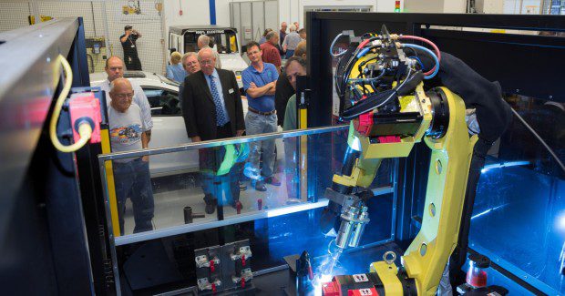
This demonstration utilizes a System 35 pre-engineered robot system equipped with the Power Wave i400, the AutoDrive 4R220, the FANUC iRVision camera and attached to the FANUC Robotics 100iC robot arm. It shows the speed and response rate in a part location application where hard fixturing is not present.
Another thing that can help you travel faster is welding either vertical down or at a 45 deg angle. Use gravity to your advantage pulling that puddle. When you’re traveling fast, you need to have that arc stability. The process needs to be able to transfer metal at a high rate and not skip a beat.
TANDEM MIG
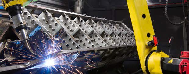
Tandem MIG welding is very similar to single-wire welding, except you have two wires and it is more expensive than single-wire welding. By introducing a second wire, you have to opportunity to lay down the same weld twice as fast, or in a heavy welding situation, lay down twice as much metal traveling the same speed. The lead wire is to generate the majority of the base plate penetration, while the trail wire performs the function of controlling the weld puddle for bead contour, edge wetting and adding to the overall weld metal deposit rate.
Tandem MIG is a dual wire, high productivity GMAW process designed for flexible robotic or fixed hard automation welding applications. The process utilizes high-speed inverter Waveform Control Technology™ to coordinate two separately generated GMAW welding arcs in unison for exceptional process flexibility. Independent control of both the lead and trail wire parameters of the tandem process allows procedure optimization for bead wetting, bead profile and penetration. Tandem MIG has proven to frequently double the production of single GMAW processes.
Tandem MIG depends on specialized power source control software that facilitates the stable operation of these two working in close proximity. The power source must be controlled to stabilize the disruptive electromagnetic influences that cause severe instability when two unregulated direct current welding arcs are operated close together.
The process works best with a large-diameter lead wire and a small-diameter trail wire. One thing to take into consideration is that the two arcs have to be synchronized in some manner; otherwise, the arc will disrupt. In addition to faster travel speeds, tandem welding also produces fewer jewels because there is less heat in the joint; it fills gaps well because it has two wires; and it’s very versatile in that you can weld many different materials, including galvanized steel, stainless steel or very thick or very thin material.
Using high-speed tandem MIG welding, you can weld up to 150 ipm. Generally speaking, high-speed tandem is used for ¼ in thick or less material as with lap welds, fillet welds, butt welds and joggle welds.
After determining how fast you need to weld and selecting your process, you need to consider what equipment you need to purchase, as well as what power source, what robot to use and how many you need. It’s important to think ahead. Be sure to select a robot that will reach to the joint, along with a torch that will provide appropriate weld access. Good high-speed welding is just as much about good fit up and good welding practices as selecting the right process.


