Inductive Proximity Sensors for Welding Applications
All inductive proximity sensors are not created equal. While the vast majority of inductive proximity sensors work well for general purpose applications, specialty inductive sensors for welding allow highly reliable sensing performance in applications where general-purpose types are insufficient. It is key to understand the limitations of a standard inductive proximity sensor and know when to select the unique performing capabilities of a special purpose sensor.
Posted: December 18, 2013
Users of inductive proximity sensors can select from a vast array of standard types to solve almost any general purpose sensing application. Unfortunately not all industrial sensing applications fall into the general-purpose category. Many applications have unique requirements, such as the need to survive in an aggressive welding environment.
What if the available mounting area is confined and even the smallest “general purpose” sensors are still too large? What if the machine being monitored is a vital piece of equipment where unexpected down-time is unacceptable? All of these are legitimate requirements in the industrial environment and specialized inductive proximity sensors exist to meet these unique needs. Each “special” application will be explored further and the available sensor solutions will be discussed.
EXTENDED TEMPERATURE RANGE
Per IEC 60947-5-2 the standard temperature rating of an inductive proximity sensor is -25 deg C to +70 deg C. Applications close to molten steel (such as welding) or glass operations may require sensors that operate above +70 deg C. It is common for manufacturers to provide sensors that have extended low and high temperature ranges in the same sensor. Ratings such as -40 deg C to +85 deg C or -40 deg C to +100 deg C are typical.
These models solve a large number of “extended temperature” requirements, but for some applications these combination models cannot meet the temperature levels needed. Other manufacturers concentrate on meeting the true extreme needs of low temperatures (down to -60 deg C) or extreme high temperatures (up to +250 deg C).
http://youtu.be/aKJMnce3o64
An overview of welding sensor issues. Poor sensor selection costs welders in every industry increased downtime, unnecessary maintenance, delayed delivery, and lost profits. Here are welding solutions that extend sensor life and increases productivity in the harshest welding environments.
High temperature-rated sensors can handle temperatures above the maximum ratings of most solid-state components. How? The vital electronics are housed in a remote-mounted module where they can be protected from direct exposure to extreme temperatures; the basic copper-wound coil is the only component that actually experiences the high ambient heat. The construction of high temperate sensors typically employs a stainless-steel housing and a cable jacket made from Teflon® (PTFE) or silicon to resist chemical breakdown at high temperatures.
IMPACT TOLERANCE
It is estimated that almost 70 percent of all inductive proximity sensor failures are caused by direct impact to the sensor face. Standard sensors are not designed to handle impact; in fact, they are non-contact sensing devices. Nevertheless, manufacturers understand the problem is often unavoidable and are continually testing various materials in an effort to create a more robust sensor face.
One of the more popular face materials used today is stainless steel. Because an inductive proximity sensor is designed to detect the presence of metal in front of the sensing coil, it seems counterintuitive that a metal-faced sensor is even possible. However, through careful engineering it is possible to “tune” an inductive sensor’s internal circuitry to ignore its metal face and respond only to external targets.
Many of these stainless steel faced sensors feature a housing that is gun-drilled from one end of a solid steel bar. Gun drilling results in a single-piece housing where the body and face are one integral unit without any seams or gaps. The housing materials vary, but most are made from 303 or 316 stainless steel. Some sensor models have a stainless steel face almost 0.75 mm thick, providing tremendous physical protection to the vital sensor coil.
In repeated impact applications such as manual part loading and unloading, these metal-faced sensors can last up to ten times longer than general-purpose inductive sensors. Metal faced sensors are available with standard, double, and even triple sensing ranges. Some target-selective versions are also available, which are specially tuned to detect “ferrous only” or “non-ferrous only” target materials.
WELDING ENVIRONMENTS
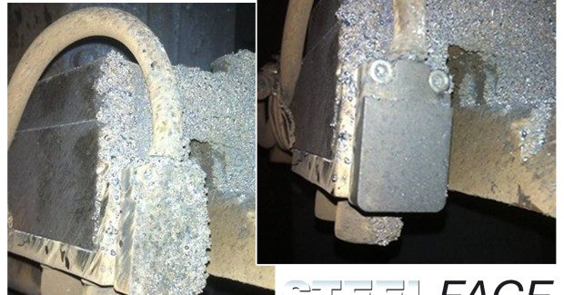
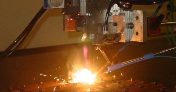
The automotive body and frame industry, the “white goods” appliance industry, and other metal-forming industries employ many welding operations to produce a final product. These weldments include frame structures, body panels and underbody support components that must be welded to properly form the subassemblies. Automated or manual “weld cells” create very hostile sensor environments due to high ambient temperatures, weld slag generation, part loading impact, and the presence of strong electro-magnetic fields.
Uniquely designed inductive proximity sensors exist specifically to survive in this harsh environment. They have WFI (weld field immune) electronics, incorporate slag-resistant body coatings (such as PTFE), and have high-temperature-rated face materials (PTFE or similar material). The faces on these sensors tend to take the brunt of the welding abuse; therefore some manufacturers offer optional ceramic-based face coatings to protect and extend the life of the sensor face.
Many WFI sensors on the market also offer multi-metal detection at the same sensing range. These sensors are commonly referred to as Factor 1 or F1 models, since they have no sensing range reduction factor for non-ferrous materials like aluminum.
Stated another way, the range reduction factor for all metals = 1.0 * the standard sensing distance for steel. Standard inductive proximity sensors typically experience a reduction in range of 0.5 or 0.4 when the target material is aluminum or some other non-ferrous material. Factor 1 sensors do not have this range reduction and offer a performance advantage to customers who have the need to detect non-ferrous metals.
SteelFace™ sensors are designed and built tough to survive longer in most abusive applications. For applications that require something more compact than a tubular sensor, the all new flatpack SteelFace sensor has a one-piece stainless steel housing offers a robust operating face for the most demanding applications. A new patent-pending coating makes it the ideal sensor choice for extreme applications.
Features of Flatpack SteelFace Sensors include:
- One piece stainless steel housing
- 5 mm operating distance (Flush)
- Factor 1 – All metals can be sensed
- Weld slag resistant W51 coating – (Patent Pending)
- Weld Field Immune
- High switching frequency
- Round corner housing
Flatpack SteelFace sensors are ideal for welding applications.
EXTREMELY COMPACT PHYSICAL SIZE
To reduce machinery weight/shipping costs and to cut costly factory floor space requirements, machine manufacturers strive to keep their equipment designs as compact as possible. These newer, smaller models are not expected to compromise on performance, in fact they are expected to outperform their larger predecessors. Additional automation
is how this added performance is accomplished, and sensors play an integral role.
Historically M8, M12, M18 and M30 tubular sensors have been the sensors of choice, but these are starting to be replaced with smaller Ø6.5 mm, M5, Ø4 mm, and Ø3 mm sensors. This new generation of mini-sensors is smaller in diameter, length and weight – all of which are important. To accommodate some of the shorter sensor housing lengths (less than 20 mm long), a separate amplifier module is often placed “in-line” with the sensor cable. This design eliminates many components from the sensor head thus allowing it to be lighter and smaller in size.
More recently ultra short Ø6.5 mm and M8 tubular sizes have come on the market incorporating fully integrated electronics. This new design eliminates the “in-line” amplifier thus saving overall space and weight. These models are available with integral cables having overall housing lengths of only 6 mm and 10 mm, and with M8 connectors having body lengths of only 18 mm.
RELIABLE DIAGNOSTICS
Reliable diagnostics are extremely important for high-throughput machines. These machines depend on the ability to identify process quality issues in real-time. The sensors on these machines need to be highly reliable and have their proper functioning guaranteed. Some sensor manufacturers are now incorporating internal sensor diagnostics that generate dedicated status outputs for monitoring via the host control system. These diagnostics allow the controller to verify the sensor’s signal integrity and monitor the “health” of the sensor itself.
Rather than experience an unforeseen sensor failure or improper signal output, the status of the sensor can be continuously monitored to recognize the need to replace or re-adjust the sensor before it fails or fails to operate correctly. This diagnostic capability allows for planned maintenance activities rather than unplanned downtime. This diagnostic functionality is now available with certain inductive, capacitive, and photoelectric sensors.
SUMMARY
All inductive proximity sensors are not created equal. While the vast majority of inductive proximity sensors work well for general purpose applications, specialty inductive sensors for welding allow highly reliable sensing performance in applications where general-purpose types are insufficient. It is key to understand the limitations of a standard inductive proximity sensor and know when to select the unique performing capabilities of a special purpose
sensor.


