Clearing the Air in Gas Delivery
MIG and TIG welding, plasma cutting, laser cutting or welding all require compressed gases. How these gases are stored, handled and used will determine the extent that the overall cost of these gas products impacts your bottom line. The correct gas delivery system will provide the most economical and efficient results to complement any of these applications – and the normal starting point for all of them is a cylinder of gas and a regulator.
Posted: February 14, 2014
Early on is optimum for looking down the road to try to project where you will be in three to five years. If additional equipment such as new cutting and welding lasers, a plasma cutting table, and MIG or TIG welding stations are to be purchased, then it’s a good bet that your single-cylinder and regulator setup will need expanding. Now is the best time to review your specific gas requirements and start planning for the future.
Cylinder regulators come in two styles, single-stage and dual-stage design. A single-stage regulator is good for applications in which the gas is used for short periods, or when there is a second point of use or “line” regulator at the work station. When using a single-stage regulator, the outlet pressure will rise as the source or cylinder pressure goes down (decaying inlet pressure characteristic). A two-stage regulator will give you stable outlet delivery pressure as the cylinder or source pressure goes down.
One of the best preventive measures that can be taken with a cylinder regulator is to mount it to a wall or vertical surface, and have a flexible high-pressure hose (pigtail) make the connection to the gas cylinder. This is an inexpensive insurance policy that will pay dividends in several ways, based on industry statistics showing that 80 percent of regulators are dropped or broken during cylinder change outs.
Another issue is gas purity. When connecting the regulator to a cylinder, there is always a “gulp” of ambient air that comes in with the cylinder hookup. This gulp will affect the gas purity at the application. When a cylinder is mounted to the wall and the pigtail makes the connection to the cylinder, the CGA fitting on the pigtail should have a check valve installed. This will minimize the amount of ambient air that enters the system with a cylinder change.
A demonstration of how to transport, secure and hook up a regulator to a high pressure gas cylinder. Also coverage of some basic things you need to do to care for your regulators and keep them in good condition and in good working order.
The other way air can enter the system is through the downstream hose used to connect the gas source to the application. Flexible polyethylene, Tygon® or other plastic hose material can and will leak in and out through a crack or small pinhole, and over time can actually leak through the material itself. By using copper or stainless tubing with a metal-to-metal seal, this will never be an issue.
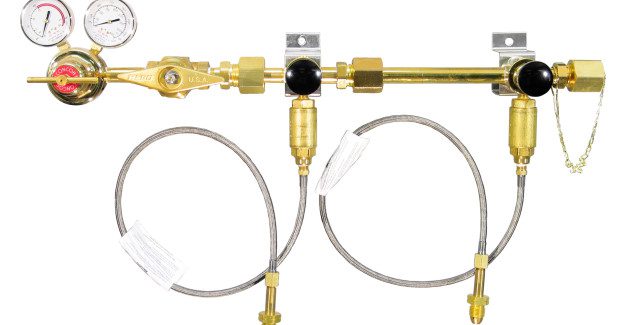
At this point, a simple manifold can be added to a wall-mounted regulator to add capacity, minimize cylinders not being utilized, and allow the operator to run the system for longer periods (see Figure 1). Manual switchovers have multiple cylinders attached to the manifold that has a pressure-reducing regulator at the outlet. The output pressure of the regulator is then set to feed into an application or piping system. By combining multiple cylinders on a basic manifold to supply an application with gas, you can minimize the time required to change out empty cylinders. A simple manifold, however, will require a certain amount of monitoring to ensure the process does not run out of gas.
The true cost of any system is how much time it will take to keep the system running. Continuous supply of gas to the application is the objective. Industry standards tell us it takes an average of 20-30 minutes to change out an empty gas cylinder with a full one. This regular interruption is a loss in productivity. When multiplied by the number of work stations in a shop, it adds up to considerable lost time. The other unseen cost is cylinder rental at $0.25-$0.40 cents a day per cylinder for high-pressure cylinders and $1.50-$3.00 per day for liquid cylinders.
The next step could be a primary/reserve switchover system in which there are cylinders hooked up to a primary side and a secondary (reserve) side. Only one side delivers gas at a time, and when the primary-side cylinder regulator reaches a pre-determined pressure set point, the system will change over to the secondary side regulator with no interruption in gas delivery. These systems can be outfitted with an alarm to notify the operator when the switchover has occurred so the empty cylinder(s) can be replaced.
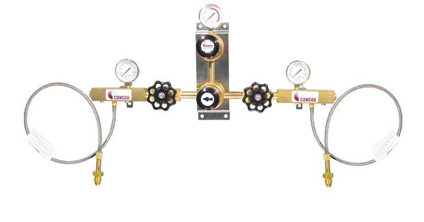
A semi-automatic switchover is also a good recommendation. These systems will involve less “babysitting” than a simple manifold with a regulator or primary/reserve system and provide continuous gas delivery to an application. With semi-automatic systems there is typically a knob or handle that will need to be rotated when a switchover has occurred and empty cylinders are to be replaced. Semi-automatic switchovers are typically pressure-differential in function and are similar to primary-reserve systems (see Figure 2).
The first regulator has two settings (300 psi and 100 psi) and a directional knob or lever to change the value, while the second regulator is set at 200 psi feeding into a common line. The first cylinder regulator set at 300 psi keeps the output of the 200 psi regulator closed. Again as the first cylinder regulator set at 300 psi empties and the pressure drops below the 300 psi setting, the second cylinder regulator set at 200 psi will open up and start to feed the system. When this happens, the directional knob or lever is rotated to change the setting of the first regulator to 100 psi, and the empty cylinder there is replaced. When the pressure in the second cylinder drops below 200 psi, the 100 psi regulator will then continue to supply the system.
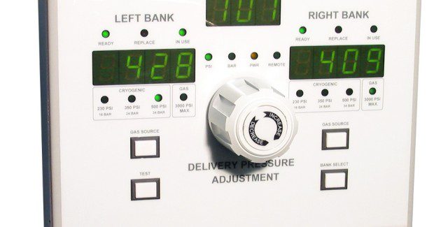
Fully automatic switchovers work off pressure sensors that monitor the right side (primary) and left side (secondary) inputs. When the inlet source pressure reaches a pre-determined set point, the system will automatically switch from primary to secondary. With a fully automatic system, only the empty /full cylinder swap out is required (see Figure 3).
At times, a mode change is the next step in efficiency. Since the gas product is at a premium in high-pressure cylinders, the best way to lower your costs would be to use a VGL (vertical gas liquid) or liquid cylinder. Liquid cylinders are essentially big Thermos® bottles capable of delivering gas or liquid product to an application. They are commonly available in oxygen, nitrogen, argon and carbon dioxide service. One liquid cylinder’s volume is equal to approximately 15 to 20 high-pressure cylinders, and it costs much less to fill one liquid cylinder than 20 high-pressure cylinders.
Liquid cylinders have a gas-use port, liquid-use port, and vent connection port on the top of the cylinder. A pressure-building circuit generates additional pressure and flow to the application, and an economizer circuit keeps from generating gas when demand is low. Safety relief valves set at 230 psi, 350 psi or 500 psi are installed on the liquid cylinder to ensure that internal pressures will never reach the point at which the cylinder could rupture or explode.
With standard liquid argon, nitrogen and oxygen cylinders, the pressure building capacity is normally around 300 scfh, with peek flow of 350 scfh for short periods. With standard liquid carbon dioxide cylinders, the pressure-building capacity is typically around 100 scfh, with peek flow of 150 scfh for short periods of time. Should the application demand more flow than one cylinder can provide, additional cylinders can be added to supply the application.
When choosing a switchover system, it’s good to remember pressure-differential switchovers do not work efficiently with liquid cylinders supplying the product. If the demand for gas is too high for a liquid cylinder to keep up with, the head pressure in the cylinder will drop below the switchover point and create a false or premature empty condition. Additionally, pressure-differential switchovers tend to leave 15 percent or more of unused product behind.
It’s worth noting that there can come a point at which the gas flow demand to an application is so great that using multiple liquid cylinders’ internal vaporizing capability is no longer practical. At this point it is good to review your gas supply options with your distributor. A bulk tank and/or an onsite gas mixer may be the best recommendation for your application.
One solution is to extract the liquid product from a liquid cylinder and put it through an external vaporizer to create larger volumes of gas product. Multiple liquid cylinders can be connected to a cryogenic manifold to feed the vaporizer a continuous supply of liquid product.
A pusher system can be used to ensure the entire liquid product in a cylinder is used, and constant pressure and flow to the vaporizer and downstream application is maintained. With a pusher system, the outlet pressure (gas) of a separate liquid cylinder (pusher) is used to force the liquid product out of the (slave) liquid cylinder(s) through the cryogenic manifold and in to the vaporizer. An uninterrupted supply of gas can then be supplied to a gas blender and a piping system by locating a pusher system on either side of a fully automatic switchover system. With the pusher system you are only limited by the vaporizer’s rated capacity to produce gas product, and the amount of cylinders hooked up to supply the application.
Another step toward efficiency and cost reduction includes installing a piping system that connects to a cylinder manifold, switchover system, or bulk tank. The key here is to size the piping and gas delivery system for the total combined pressure and flow required at all the use points. This must be done to prevent “starving” any of the downstream use points. When sizing the piping system, it is important to use the correct size pipe or tube to ensure the gas pressure and flow will not be restricted.
Considerations for future expansion of the piping system should be discussed before the size of the piping is selected. Since the difference in cost of materials is minimal, it’s a good idea to err on the side of caution and use a larger size pipe or tube.
There are two types of piping systems, dead-end or looped. With a dead-end system the piping system starts at the cylinder manifold and ends at the last drop or use point. With a looped system there will be two ways the gas can travel to the last use point. By using the correct size pipe and by looping the gas piping system, you can ensure that none of the use points will be affected if there is a large flow demand at one location.
With a clearer understanding of the gas delivery systems currently available, you should now be better equipped to select the correct gas handling system for your application.


