Welding with Laser Touch Sense
Because of its low cost and ease of use, laser touch sense is quickly growing in popularity to locate weld joints and parts that are moving in location relative from one part to the next.
Posted: February 19, 2014
Laser touch sense has advanced in the past couple years. There are several solutions that are able to locate weld joints and parts that are moving in location relative from one part to the next. 2D and 3D vision, real-time seam tracking and wire touch sense all come to mind. There is one solution, however, that is quickly growing in popularity because low cost and ease of use. Its name is laser touch sense.
If you’re one of the lucky people that has been able to attend any industry trade shows in the past two years, you might have witnessed a demonstration or two of this type of weld joint finding solution and understand its potential power. If not, I will do my best to describe it to you in this article.
First, let me begin by saying that one of the biggest advantages to laser touch sense is the ease of programming. No laptop is required, only the robot teach pendant – a device that can be used to remotely control a robot – and the understanding of traditional wire touch sense. For anyone who has not programmed a robot or touch sensing, I can tell you it’s truly not that difficult.
Robots are becoming “demystified” in the workplace. More and more people are learning robotic skills every day. If, however, your workplace has no one with robot experience and plans on buying robots, I recommend shopping around and purchasing robots from companies that offer several days of training for multiple individuals for each robot purchased. Even though robots are easy to work with, it’s important that people become comfortable with operating them before your robot lands on your production floor.
The second important feature is that laser touch sensing works on heavy mill scale and on aluminum applications. These two areas are traditionally problematic applications for contact wire touch sense. The laser has no problem with either. The heavy mill scale on steel and the aluminum oxide that naturally forms aluminum are often insulators that prevent conventional wire touch sense from working 100 percent of the time.
For the reason mentioned above, traditional touch sensing that uses the welding wire to locate the weld joint/part is usually limited to ferrous type materials with a suitable weld joint/part design. New laser sensor technology developments now allow for the use of a laser beam to locate the joint/part with great accuracy.
Commonly used digital and analog cards located within the robot cabinet read digital and analog input information from the laser sensor amplifier device. Digital outputs are used to turn the laser on and do calibration functions.
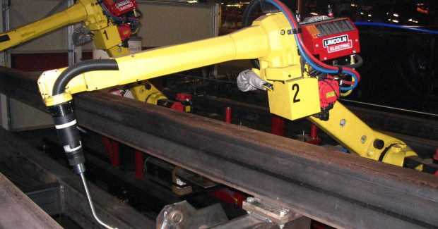
A laser sensor head that creates the laser beam is attached to the end of the robot arm near the base of the welding torch. A small cable will connect the laser head located on the end of the robot to the laser sensor amplifier/display that is installed somewhere within the weld cell. The sensors’ primary function is to power the laser head, process the returned laser beam signal, communicate to the robot if the part has been found, and to display analog position data. It is also where you would change the factory settings to possibly tailor the laser for your desired application.
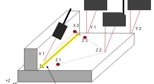
Normally, only the welding torch would require a tool center point. However, with laser touch sensing, the laser beam spot also requires a tool center point. Makes sense if you think about it. What you’re actually doing is “reading” joint/part positional information (X, Y, Z) with the laser beams analog (distance) and/or digital (on or off) functions.
The beam position information, through the robot encoders, gathered weld joint position information by touching edges and surfaces during the search function created by you the robot operator. These “search functions” provide the welding torch tool center point (end of the welding wire) for accurate weld placement for each weld.
My experience has been that in a production environment that differences as small as 1.0 mm can be recognized and depended upon. The laser may have a resolution of .1mm, but you could never count on this small of a resolution to provide repeatable results in a production environment. Always make sure that your laser touch sense process is robust by allowing generous resolution between a “on” and “off” laser reading. We use 1.0 mm difference minimum on all of our applications.


