CAD/CAM Sheet Metal Fabrication Software: The Latest Trends and Advances
These new systems showcase how CAD/CAM software for sheet metal and structural steel fabrication is coming of age to meet the increasing needs for speed in job shops, contract manufacturers and metal service centers.
Posted: April 23, 2014
INTELLIGENT CAD/CAM PROGRAMMING FOR CUTTING APPLICATIONS
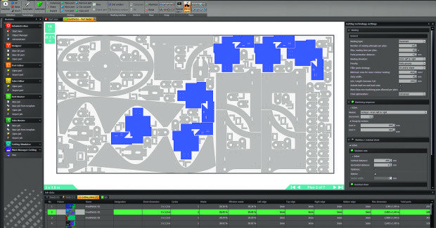
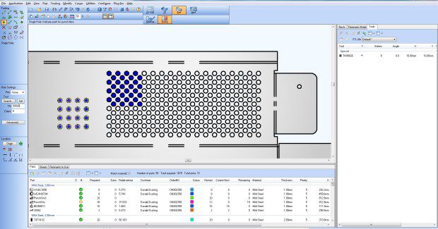
ESAB Cutting Systems (Florence, SC) offers Columbus™ III, an intelligent CAD/CAM programming package designed to streamline workflow and improve cutting machine productivity. Columbus III software offers user-friendly, standardized interfaces and numerous features to make programming easier and more efficient, improve material utilization, and increase productivity.
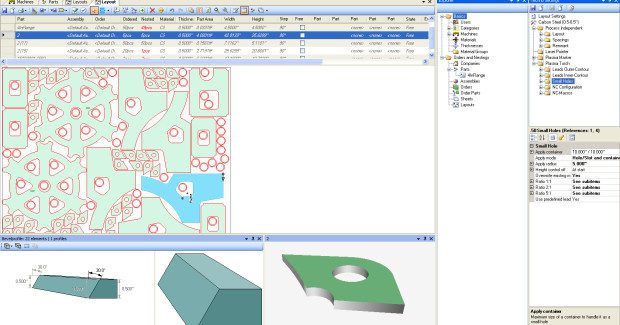
An overview of Columbus III software.
A powerful database-driven programming and nesting software specifically designed for plasma, oxyfuel, laser, and waterjet cutting, Columbus III is the first cutting software package developed and maintained by a cutting machine manufacturer. It supports straight and bevel cutting as well as all current marking devices. At the heart of the software is a menu-driven, easy-to-use interface that provides complete control over the entire programming process.
Columbus III supports Precision Hole Technology™ that automatically generates the best possible program code for cutting small holes and slots. This technology is automatically applied when cutting mild steel up to one-inch thick. No programmer intervention is required to produce high quality plasma holes. Precision Hole Technology applies to mild steel up to one-inch thick, on holes from 1:1 up to 5:1 diameter-to-thickness ratio.
Columbus III is a modular package that can be scaled to meet the cutting application, providing the flexibility to adapt and expand the software as required. Software modules include automatic nesting to maximize plate utilization, bevel programming for efficient contour and straight programming of oxyfuel, plasma and laser bevel heads, plate and subassembly management for unique plate identification and faster processing of jobs containing subassemblies, and more.
Columbus III uses the state-of-the art Microsoft® SQL platform as the backbone for all of its databases, ensuring programming changes, updates and improved features will be quick and easy. The Columbus III software package forms part of a process control system that includes the m3 Plasma™ system and Vision® T5 control that work together seamlessly to provide the highest cut quality on all contours with fully automated process control from part concept to completion.
ESAB Welding & Cutting Products, PO Box 100545, 411 South Ebenezer Road, Florence, SC 29501, 888-372-2288, www.esab-cutting.com.
CAD/CAM NESTING SOFTWARE INCREASES CUT PRECISION AND PRODUCTIVITY
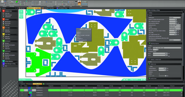
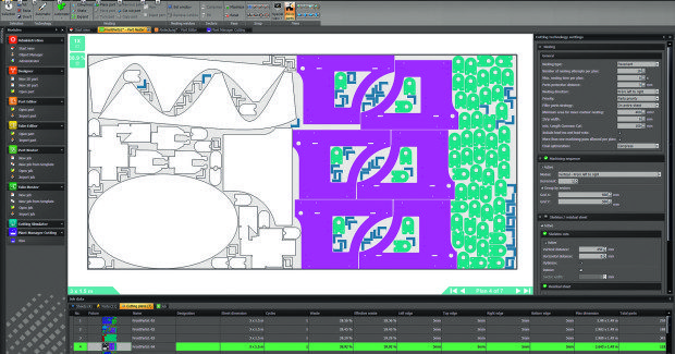
Hypertherm, Inc. (Hanover, NH) offers its enhanced TurboNest® and NestMaster™ CAD/CAM nesting software that make it even easier for shops that fabricate or cut metal to increase the cut quality, productivity, and profitability of their operations. Added features and enhancements include:
- Support for CAD fonts. TurboNest now supports native AutoCAD® fonts (SHX) and Windows® system fonts (TrueType, OpenType, PostScript) for CAD drawings that contain text.
- 2D CAD cleanup. The enhanced 2D CAD program in TurboNest can make quick changes to any CAD drawing before it is added to the part list.
- Unicode fonts for CAD text. NestMaster now supports Unicode fonts for CAD drawings that contain text.
- 2D CAD multi-drawing support. Multiple drawings can be open simultaneously in 2D CAD in NestMaster.
A demonstration of how to create stencil letters with Hypertherm CAM (Nestmaster, Turbonest and Pronest).
Version 10.1 is available at no charge to anyone with an active TurboNest or NestMaster software subscription. Customers simply need to visit the Online Knowledge Base at www.hyperthermcam.com. ProNest, NestMaster, and TurboNest have been industry-leading nesting software for two decades, offering best-in-class performance and reliability with a straight-forward, easy-to-use design. ProNest is also a component of Hypertherm’s Integrated Cutting Solutions that provides support for True Hole™ and Rapid Part™ technologies.
Hypertherm, Inc., PO Box 5010, Hanover, NH 03755, 603-643-3441, www.hypertherm.com.
WATERJET CAM SOFTWARE SIMPLIFIES COMPLEX PART CUTTING
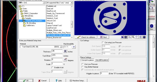
OMAX Corporation (Kent, WA) has developed a highly advanced computer-aided manufacturing (CAM) software tool that further simplifies the cutting of complex, precision parts on its JetMachining® Centers. Free to OMAX owners, Intelli-CAM software interfaces directly with the company’s intuitive Intelli-MAX® Software Suite to easily generate 3D tool paths from solid 3D models as well as quickly perform 3D to 2D file conversions.
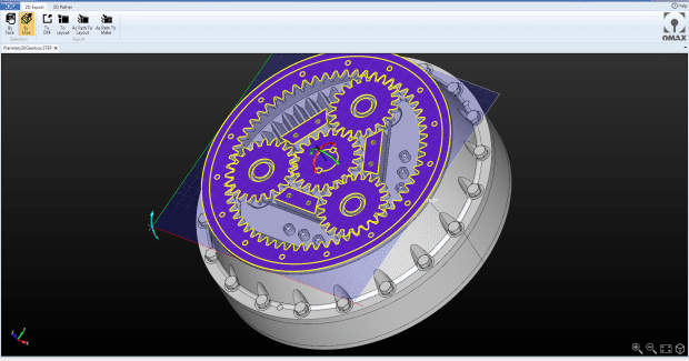
An overview of the intuitive OMAX Intelli-MAX Software Suite that is designed specifically for abrasive waterjet cutting.
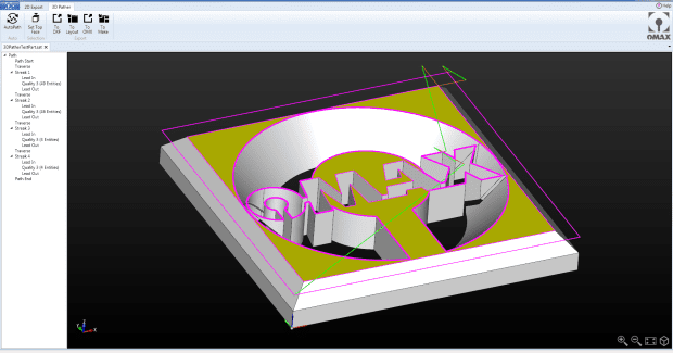
Intelli-CAM, through its 3D Pather tool, quickly generates multi-axis, machine-ready tool paths from complex 3D solid models. In fact, Intelli-CAM automatically recognizes viable cutting surfaces from those 3D shapes, including variable bevels and tilted cones. This special functionality eliminates the need to manually add 3D attributes to a 2D file, thus allowing users to significantly reduce their production times.
Offered as a free update for existing JetMachining Center owners, Intelli-CAM operates as a standalone application or in tandem with several of the popular third-party 3D CAD systems. It supports a wide range of neutral and native 3D file formats – CATIA, SolidWorks®, Solid Edge, Autodesk® Inventor®, Siemens® NX, Pro/E®, Creo®, Step, IGES, VDA-FS, ACIS, Parasolid®, 3D DXF and DWG – so that users avoid having to purchase expensive CAD software filter packages. Intelli-CAM also supports direct interface with CAD software such as SolidWorks, SpaceClaim®, Inventor, and Rhinoceros®, which allows users to launch Intelli-CAM directly from those applications.
According to Carl Olsen, the lead software engineer for OMAX, Intelli-CAM allows the Intelli-MAX Software Suite to support just about any 3D or 2D CAD file or artistic drawing. “Our job shop customers will greatly benefit from Intelli-CAM as they will rarely ever again have to ask their customers to re-save a file to a format they can accept – because they can now accept nearly all of them,” he said. He also noted that customers doing 3D programming for 5-axis waterjet cutting will find Intelli-CAM greatly simplifies those operations as well, suggesting that Intelli-CAM “may be the easiest to use 5-axis CAM software ever, and it’s free.”
The version 20 launch of Intelli-MAX Software Suite makes it possible for owners to improve the speed and memory utilization of their waterjets as well as have access to new tools that allow for increased operator efficiency. Olsen explained how the Intelli-MAX Software Suite sets OMAX apart from the competition. “This proprietary software, which we continuously update and improve, requires minimal operator training and makes it easy for users to create precision parts faster and at a lower cost. Not only does the software simplify the control of the jet stream while cutting, it also automates programming and tool setup work,” he said.
The automatic tool path planning engine in Intelli-MAX 20 improves the artificial intelligence of the waterjets, creating less need for operator involvement, improved collision avoidance functionality and more efficient traversing between parts. A scripting engine has been added to Layout, the specialized CAD portion of the Intelli-MAX Software Suite from OMAX that allows users with advanced programming skills to create standalone applications for automating their machines. For example, users can add barcodes to documents that, when scanned, the information is automatically built into the cutting parameters of the control software.
The scripting engine also extends the commands of the CAD applications, which users can further leverage through fee-based custom programming services. Other functions of the Intelli-MAX 20 include a circular window, bridging and capping commands, improved advanced 3D machining features, enhanced machine monitoring and alerts as well as parametric shapes for easier 3D pipe cutting.
The Intelli-MAX 20 Software Suite, which is free to all existing JetMachining® Center owners, is backed by the company’s unparalleled support. By continuously adding and updating its help screens, users have access to over 2,000 pages worth of the latest tutorials, troubleshooting guides, and tips and tricks directly at the control.
OMAX Corporation, 21409 72nd Avenue South, Kent, WA 98032, 800-838-0343, www.omax.com.

