CNC Collision Avoidance
Sound the Alarm: More advanced CNC units provide full collision avoidance for both the machine builder and the end user alike, thereby protecting both the machine and the operator.
Posted: April 23, 2014
Collision avoidance seems intuitive to any machine builder or user, but it’s how we get there that’s changed dramatically in recent years. Many controls have some sort of alarm mechanism and the programming of machine limit switches was traditionally a key safeguard. We all know those didn’t always work.
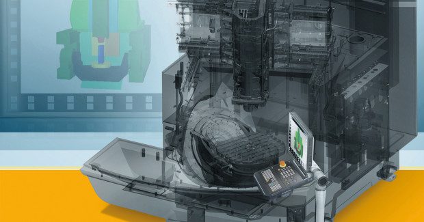
Today, on the more advanced CNC units that are available, full collision avoidance can be provided for both the machine builder and end user alike, thereby protecting the machine and operator alike. In the machine design phase, the full cycle simulation is combined with real-time monitoring of all moving and stationary components on the machine. This has particular importance when tombstone fixturing devices, rotary table trunnions and other hardware are present inside the cutting theater.
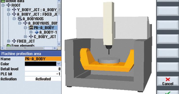
Moreover, on the builder’s workstation using an offline PC – whether working in NX, Catia or and other CAD/CAM design platform – the builder engineer can define cubes, spheres, cylinders or STL files to model all of the machine assemblies and structures relevant to determine full collision avoidance. Plus, this can be done in all operating modes, including JOG/MDI and AUTO, with identifiable selection and deselection programmable, further protecting the machine in the field.
A demonstration of how machine tool builder Heller achieves realtime collision avoidance with SINUMERIK Collision Avoidance.
Since a full, solid model of the machine is used for all software calculations, this advancement represents a true 3D visualization process of machine motion and cycle characteristics alike. Because this collision avoidance on a virtual machine can be created within the design phase, it becomes a useful tool for machine builders as well as fixture and tooling designers.
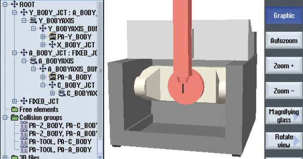
In the shop, using the operating program and HMI on the CNC can further identify potential collisions when altering a program, changing a rotary table dimension, resetting a fixture or simply monitoring the tooling changes. Basic machining areas and limits can be defined by modeling those protected areas. The CNC automatically alerts a potential collision by highlighting the relevant structure of the machine onscreen. Headstock, spindle, rotary table trunnion, tombstone fixturing or a simple clamp position can be monitored in this real-time collision avoidance program.
This powerful 3D real-time collision avoidance monitoring can be done on any machine, including a true 5-axis simultaneous multitasking mill/turn machine with a B-axis and the most sophisticated gantry/rotary table assemblies in the market. All of the stationary and moving elements, as well as the tool cutting edges, are effectively monitored for potential collision. Once again, the effected areas or machine components are quickly identified onscreen during a cycle simulation or in real time.
Human error can also be factored in so that the resulting collision that would have been caused by a change in a program or a set-up error can be anticipated, triggering an alert that is sent to show and highlight the effected area onscreen.


