From Days to Minutes
To dramatically shorten design-to-manufacture time, this advanced 3D simulator unveils powerful real-time visualization with collision detection that speeds tube bending program development so that shops can optimize their computer-controlled bending machines.
Posted: September 9, 2014
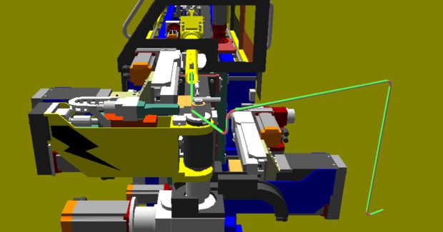
Unison Ltd. (North Yorkshire, UK) has launched an advanced 3D simulator to help metal fabricators accelerate the development of control programs for all-electric tube bending machines. Using artificial intelligence techniques, the simulator provides powerful program analysis and optimization facilities, together with realistic real-time visualization of the tube bending process.
The simulation software is valuable in almost all tube bending applications, but can be particularly helpful for fabricators quoting on jobs and planning production, in reducing design-to-manufacturing times to help speed product delivery, and on any application involving tubes manufactured from expensive alloys. Customers with several Unison machines can also use the software to choose the most appropriate machine for bending a particular part.
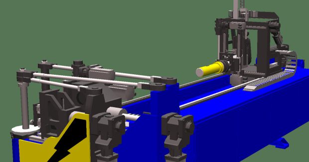
The new 3D simulator is based on true CAD (computer-aided design) models of the target machines, resulting in exceptionally detailed computer-generated imagery. The simulator is designed specifically to help users develop high quality production-standard tube bending programs without the need to test and optimize them on the target machine. Used in conjunction with Windows-based Unibend control software, it enables fully validated bending programs to be created entirely off-line, and is suitable for any machine in the Breeze range of all-electric tube benders.
One of the most time-consuming tasks normally faced by users is structuring the program to prevent any collisions between the tube and the bending machine, or its surroundings such as the production floor. It is difficult to visualize the combined effect of tube feed and rotation, and the movement of machine tooling such as clamping and pressure dies, and the bending head.
The problem becomes more acute as the length of tube, or the complexity of bends, increases. As a result, optimizing the program’s bending sequence and incorporating any necessary correction feeds for collision avoidance is usually an iterative task demanding valuable machine time. It also invariably involves producing trial parts, creating unnecessary scrap material.
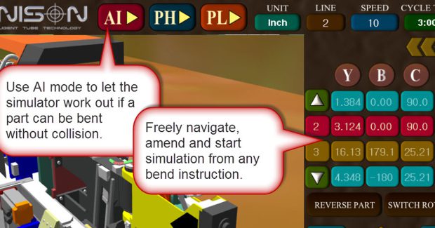
This 3D simulator incorporates fully automated collision detection capabilities and offers a choice of real-time or batch operating modes to create error free bend instructions. In real-time mode, simulation can be paused at any time and can be started from any bend; changes made to bend instructions will cause the simulator to re-evaluate the motion profile of the machine – ensuring that the simulator always mirrors the sequences used on the real machine.
In batch mode, the simulator will study a directory tree and process all bend instruction files in that tree; parts that can be bent will be stored in a designated folder and parts for which the simulator could find no collision-free solution will be stored in a quarantine folder for further analysis by production or design teams. During beta trials of the simulator, one customer reported that by using batch mode they had fully analyzed and verified the bending programs for 300 parts in four hours – a task that previously took up to five working days due to the need for machine time, and operator involvement, to trial every part.
Without simulation, ascertaining whether it is even possible to bend a part on a particular machine can take several days. After creating the part model on a CAD system, the designer processes the data using the system software to create an YBC file which defines each bend in three dimensions. The file is then transferred to the machine where it runs under control of Unibend software – the operator is responsible for checking if it creates the desired part. Any need for changes are fed back to the designer, and after modification the program is tested again on the machine. This process often needs to be repeated several times to resolve successive problems.
The 3D simulator shortens the design-test-optimize process dramatically, eliminating the need for a bending machine and its operator until manufacturing commences. For example, designers can now typically verify whether a part can be bent within about three minutes. The simulator accepts the same YBC file that is normally used to control the bending machine and runs it offline, to create a motion profile that defines how each axis on the real machine will move.
The designer can then simulate the part to check its design. The simulator’s physics engine has access to a database containing configuration details of every machine in the Breeze range of tube benders, together with comprehensive performance data for all motorized axes, enabling the computer-generated imagery to be controlled accurately and realistically
Users can save the results of simulations and rerun them at any time for comparison purposes. Artificial intelligence (AI) techniques are employed to help users select the most efficient bending sequences and optimize them to minimize machine cycle time. The simulator’s AI is aware of the capabilities of the machine and can work through all permutations very quickly. Furthermore, if customers have specific ‘rules’ that they want including in the AI, these can be incorporated easily since it has already been implemented as an option for several customers.
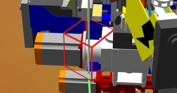
It is very important to ensure detection of every collision, which is the reason this software uses a custom physics engine that is accurate to 0.005 mm. Even though this is in advance of the mechanical accuracy of real machines, customers surveyed opted to have highly accurate simulation, with the option to ‘ignore’ a collision rather than use a tolerance which could lead to missed collisions. All types of collisions are detected in the simulator, including tube on tube, tube on environment, tube on machine, machine on machine and tube spring-back.
To maximize bend accuracy, the simulator factors in the tendency for metal tubes to spring back after being bent. There are two elements to spring-back correction: a proportional element which is determined by the programmed bend angle, and a fixed element which depends on the type of tube material and its size and thickness. The value of the fixed element is based on empirical data held in a materials database, which the user can update when testing new batches of raw material, or as a result of sampling production parts under a quality assurance program.
According to Unison’s Jim Saynor, “Real-time 3D simulation of tube bending allows metal fabricators to achieve significant cost savings through much faster program development and reduced scrap. We believe that our new simulator provides a much more detailed and realistic portrayal of machine performance than competitive software, providing users of Unison all-electric tube benders with a major business advantage.”
Unison Ltd., Thornburgh House, Scarborough Road, North Yorkshire, Y011 3UY UK, 44(0)1723-582868, sales@unisonltd.com, www.unisonltd.com.
Horn Machine Tools, Inc., 40455 Brickyard Drive, Madera, CA 93636, 559-431-4131, www.hornmachinetools.com.


