Automating the “Feel” in Deburring and Edge Finishing
Quantifying and adapting the “feel” of the abrasive against the part is a critical step toward successfully automating this labor intensive offhand operation.
Posted: November 5, 2014
To sustain profitability in today’s competitive market, manufacturers are increasingly examining options for automation. Many advanced options are now available to move far beyond the well-known “pick and place” tasks of traditional robots. Six-axis robots are a popular solution for much more complex tasks, including advanced material handling, painting, and spot welding. And as further enhancements continue in offline programming, vision systems and sophisticated end-of-arm tooling, shops can be well served by automating traditional labor intensive processes.
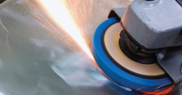
Take deburring and edge finishing, for example. This process usually requires an operator to manually introduce the work piece to an abrasive media or, in other instances, the abrasive media is brought to the work piece with portable hand held tools. Abrasive media, typically seen in deburring, fall into three categories and are available in various shapes:
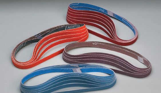
- Coated Abrasives – belts, discs, flap wheels, specialty shapes. Coated abrasives are comprised of a resin and abrasive mix applied to a backing, generally a cotton or polyester cloth (see Figure 1).
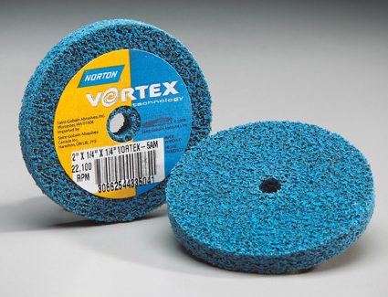
- Nonwoven Abrasives – wheels, belts, discs. Nonwoven abrasives are also a mixture of resin and abrasive grains, but is applied to a fibrous material which can then be formed (see Figure 2).
- Abrasive Brushes – radial wheels, cup wheels.
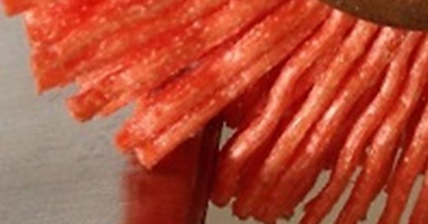
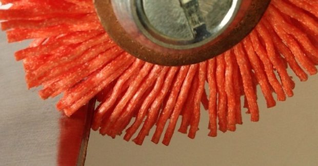
In wheel form, the fiber acts as a bonding system that wears away with product use. In belt or disc form, a backing (or “scrim”) is used in a similar fashion to a coated abrasive. Abrasive brushes utilize abrasive-impregnated nylon filaments configured to a wheel (see Figure 3)
Most of these tools are used in a manual setting that increases not only the risk for operator injury, but also the time and overall cost of the operation. Due to these challenges, shops are increasingly shifting to automate them, with each application presenting a unique set of circumstances. Since many of these operations are based on an operator’s interpretation of “feel” of the abrasive against the part, it can be difficult to make this transition. However, the “feel” of an abrasive media is quantifiable in terms of cut rate, wear rate, compliance, and conformability – which means a good understanding of these attributes is important as a shop takes steps toward automating this process.
MATERIAL REMOVAL RATES (MRR)
The cut rate of an abrasive is also known as its “material removal rate” and can be used in terms of volume (cubic centimeters per minute) or weight (grams per minute). For any given abrasive, this value will vary with material, the amount of force in the cutting zone, and the speed of the abrasive (which affects the forces in the cutting zone).
MRR is the key piece of information used in determining achievable cycle times for processing a given part. One simple test commonly used by our application engineers is recording the work piece weight before and after grinding, and the total grind time, or contact time. Material removed divided by grind time gives the rate at which material is removed. This is the MRR. Variations of this simple test method can provide valuable insight into feasibility studies when determining how to process a particular component.
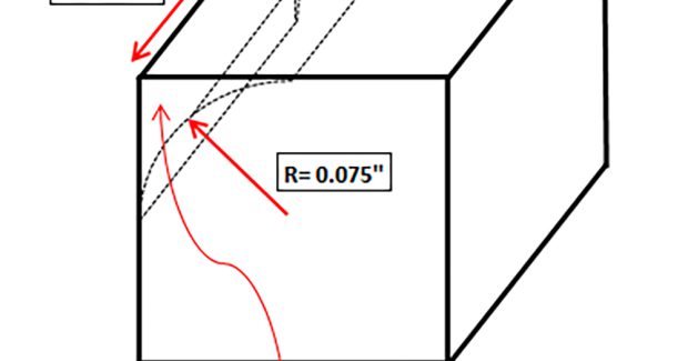
It is also helpful to quantify the amount of material to be removed from the work piece. The schematic in Figure 4 shows an approach that can be taken to define the volume of material to be removed to generate a 0.075 in radius. Once this volume is determined, an abrasive or sequence of abrasives can be chosen based on their material removal rates and the allowable cycle time. Figure 5 demonstrates an example of product mapping that compares the material removal rates of four nonwoven discs of different aggressiveness; “coarse” being the most aggressive and producing the roughest surface finish, and “very fine” being the least aggressive and producing the finest surface finish. This data can then be used to make informed decisions when selecting a product for the process.
One of the most significant variables that will affect MRR is the type of grain used in the abrasive product. Speaking in general terms, there are three major types of conventional abrasives used for deburring:
- Aluminum Oxide
- Silicon Carbide
- Ceramic Alumina
When selecting a product for an automated system it is important to consider that, in these general terms, ceramic alumina grain has better MRR and longevity characteristics than its silicon carbide and aluminum oxide counterparts. Using a premium grain may be required to maximize the efficiency and reduce overall costs in the operation. Though the products may be more expensive, the abrasive costs are negligible in comparison to the savings associated with reduced cycle times.
Keeping material removal rates in mind, Figure 5 demonstrates performance mapping of four Nonwoven Vortex Rapid Prep discs on 718 Inconel. Collecting this technical information is a step toward selecting the best suited abrasive for the application.
WEAR RATES
Wear rates are an indication of how quickly an abrasive media reaches its so-called “end-of-life,” which varies depending on the abrasive and the work piece. How quickly these conditions are reached and at what rate are important factors to take into consideration when developing an automated system. Some examples that characterize the end of the abrasives usable life may include:
- Significant reduction in MRR; geometric tolerance requirements not being achieved.
- Surface finish requirements not being achieved.
- Reaching wheel stub size.
When wear rates are determined, programming or feedback measurements can be put into place to account for these changes. Examples of these could be:
- Software programming that increases the penetration into an abrasive brush face by 2 percent after ten cycles to maintain a required cut rate.
- Counting programs that are predetermined to signal an abrasive media change based on the number of cycles an abrasive media can maintain a surface finish.
- Probing or vision devices that can account for the reduced diameter of an abrasive wheel.
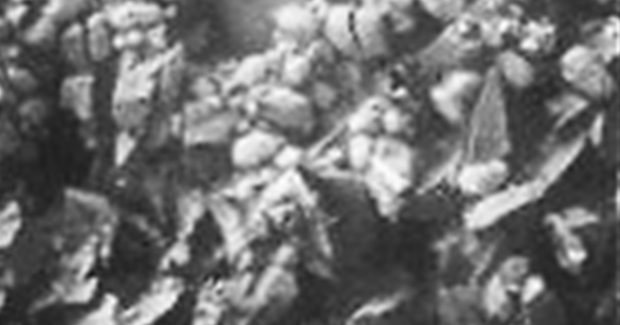
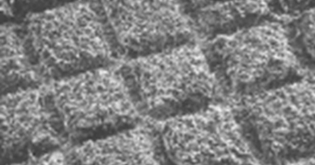
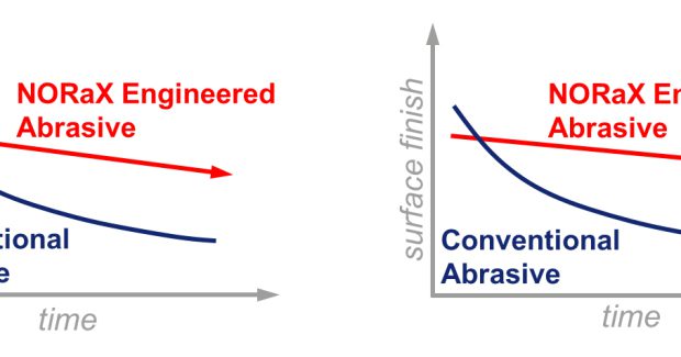
When compensating for wear characteristics, the consistency of the abrasive plays a major part in the outcome of the final results, especially for tighter tolerances. As an example of using wear rates, the magnified view in Figure 6 shows a conventional abrasive structure and the magnified view in Figure 7 shows a NoRaX engineered abrasive structure. These are both classified as coated abrasives.
The NoRaX controlled pattern allows for consistent cut rate as well as surface finish and will follow trends as shown in Figure 8. Understanding that wear rates of engineered coated abrasive follows a more linear trend will increase the controllability of the automated process.
COMPLIANCE AND CONFORMABILITY
Although similar, compliance and conformability refer to different parts of the automated system. Compliance, typically used when describing fixturing or tooling, refers to the ability to control the amount of force between the work piece and the tool. This is often achieved with a combination of pneumatic cylinders and/or mechanical-electrical controls that regulate the air pressure or electrical current and thus, the force at the grinding interface.
For example, think about a robot carrying a work piece to an abrasive belt grinder that is outfitted with a constant force pneumatic cylinder to allow it to “give” when force is applied. This “give,” or compliance, allows the force to be nearly constant at the area of contact between the work piece and the belt, assuming the area of contact does not change. Even if the robot’s position accuracy or repeatability is ±0.002 in, the compliance can help account for this variations by allowing an interference to be programmed at the area of contact. This is also true for situations where the tool is compliant and brought to the work-piece.
Overall, it helps to increase the accuracy and consistency of the results of the robot by allowing for positioning error at the tool center point while maintaining an acceptable force. In terms of abrasives, this allows the system to control the MRR. Compliance fixturing and tooling is well known among robotic manufacturers and integrators.
Conformability is the ability of the abrasive to match, or reach, the various contours and intricacies of the work piece. A nylon abrasive brush conforming to a corner, edge or complex geometry is a good example (see Figure 9). Each filament has the flexibility to bend and pull across the work piece and introduce the abrasive grains, taking small repeated cuts until the edge finish condition is reached. These two attributes are especially important when finishing irregular features. Generally, the more complex the features are to deburr, the more conformability and compliance will be required in the system.
CONCLUSION
In summary, automating a manual operation can pose several unique difficulties, based on the incoming work piece and its finish and geometric requirements, but the benefits of reduced costs and increased safety for operators, far outweigh the difficulties. From an abrasives standpoint, adapting the process to fit the specific needs of the application can be made manageable by identifying, understanding and quantifying these four key characteristics:
- Material Removal Rate (MRR)
- Wear Rate
- Compliance
- Conformability
With these key elements, the transition from an offhand operation to an automated abrasive process can be successful and profitable.

