Automated Friction Stir Welding
Because its low heat input and high strength provide opportunities to redesign structures with increased tensile strength, outstanding fatigue properties, improved corrosion resistance and minimal distortion and shrinkage, FSW could change the way trains, trucks, cars, aircraft and aerospace components, and other common aluminum structures are built.
Posted: February 27, 2015
The Welding Institute, Ltd. (TWI; Cambridge, UK) invented friction stir welding (FSW) in 1991 and my company produced the first purpose-built friction stir welding machine for a Norwegian shipbuilder in 1996. FSW has the potential to change the way many common aluminum structures are built, notably trains, trucks, cars, aircraft and aerospace components, including the NASA/Boeing Vertical Launch System (see below). The low heat input and high strength of automated friction stir welds provide opportunities for manufacturers to redesign their structures with increased tensile strength, outstanding fatigue properties, improved corrosion resistance and with minimal distortion and shrinkage.
SUCCESSFUL APPLICATIONS
Material thickness can range from just under 1 mm and up to 70 mm. All common grades of aluminum have been successfully welded using FSW, as has copper. In fact, SKB (Stockholm, Sweden) has proposed sealing Sweden’s nuclear waste in copper canisters and has successfully friction stir welded 5 cm copper. Currently, the best candidates for FSW are long, longitudinal joints in butt, lap and combination butt/lap joints on aluminum.
http://youtu.be/cYxoC7-OP5U
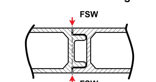
There are two primary reasons these configurations work best. First, these joints do not require the addition of a filler metal, which is not possible with current systems. Second, the process requires a significant amount of downforce (up to 200 kN, with forces in the range of 20 kN to 40 kN (2,250 ft-lb to 22,000+ ft-lb) being common for material in the 8 mm to 12 mm thickness range. The process also generates significant lateral forces. Containing the forces generated during FSW requires careful consideration when designing fixtures and clamps; rigidity is essential. Engineers and designers can also play a role in managing these forces by working with aluminum extruders to develop profiles and channel shapes that better support the FSW process. Figure 1 and Figure 2 provide some examples.
To produce a solid butt weld, note that the FSW process works best with minimal gaps (≤10 percent of the material thickness), and that corner roundness should be reduced. Some end-users mill the profile edge to improve geometric accuracy. While flat linear joints are ideal, they’re not exactly common in automotive applications, where complex structures require a flexible working envelope. To weld challenging joints, the Rosio system has been developed to use an ABB IRB 7600 robot modified for FSW. These robots can apply a down force of up to 13 kN (2,922 ft-lb), suitable for welding 5xxx aluminum up to 6 mm.
As with every new technology, potential adopters always have one question: Who else uses it? Today, more than 300 users license FSW technology. In the automotive world, FSW successfully welds suspensions, seat parts, bumpers and wheels in commercial applications. Aviation and aerospace users include Boeing, Spirit, Lockheed Martin and EADS (now Airbus Group). Rail applications (floors, sidewalls and roofs) include those with SAPA in Sweden and China North Rail, Toshiba and China South Rail in Asia. Transportation applications also include telescopic lift booms. Made of four 7000 Series profiles, the booms are 8.5 m long, have a thickness range of 5 mm to 10 mm and are welded at speeds up to 1 m/min.
THE FUTURE OF FILLET WELDS
In standard FSW, both the pin and shoulder rotate. Coupled with the need to add filler metal to achieve sufficient throat depth, the process is unsuitable for fillet welds. To that end, a TWI group-sponsored project is currently focused on developing a new technique called AdStir, or Stationary Shoulder Friction Stir Welding (SSFSW), which includes adding afiller material to form a reinforced fillet weld. Additional research has been performed at the Chalmers University of Technology (Gothenburg, Sweden) and initial results indicate a good future for the development of SSFSW systems. However, at this point, this process is still in the R&D phase.
Proven benefits of FSW include significant weight savings, superior tolerances on shapes and components, reduced on-site machining and reduced cycle time through faster weld speeds and lack of post-weld cleaning. The process does not generate arcs/rays, fumes or spatter (e.g., a safer and more green technology), and there is no need for post weld heat treatment. Further, because of the reduced heat input compared to traditional arc welding processes (GMAW for transportation, GTAW for aerospace), FSW reduces the possibility for weld defects. In short, the process has proven its benefits.
BOEING SELECTS FSW FOR SPACE LAUNCH SYSTEM
When the Space Shuttle Atlantis retired in 2011, many Americans wondered about the future of the country’s space program. Today they have an answer with NASA’s new heavy-lift rocket, the Space Launch System (SLS), being manufactured in conjunction with Boeing and using the FSW process for manufacturing the main core stage fuel tank structures.
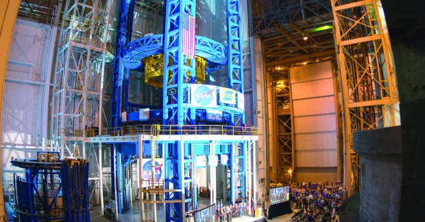
ESAB is completing the world’s largest spacecraft welding tool for the SLS. The Vertical Assembly Center (VAC) is a giant circumferential welding system that uses FSW to precision weld the fuel tank structures for the rocket. The VAC stands 170 ft tall (52 m), is 78 ft (24 m) in diameter, and weighs 3,000,000 lb. Built at the ESAB facility in Laxa, Sweden, and supported by the company’s North American Automation Division, the VAC will weld the domes, rings, and barrel sections to form the core stage of the SLS, the most precise part of the rocket assembly. The core stage will tower more than 200 ft tall (61 m) with a span of 27.6 ft (8.4 m), and is designed to store cryogenic liquid hydrogen and liquid oxygen that will feed the rocket’s four engines.
The construction of an assembly of this magnitude requires entirely new ways to fabricate, assemble, and weld the main fuel tank structures. The VAC is capable of supporting the huge rocket fuel tank while circumferentially welding its sections together using the friction stir process. A precision welding tool, its weld head and clamp positional accuracy and repeatability hold a weld tolerance of less than 0.015 in. This unique welding system will revolutionize how the massive launch vehicle is produced and will lower manufacturing costs.
The first SLS mission is expected to launch in late 2017 or early 2018. The SLS will be NASA’s first exploration-class vehicle since the Saturn V took American astronauts to the moon more than 40 years ago. It will provide new opportunities for space exploration beyond Earth’s orbit. With its superior lift capability, the SLS will allow travel to explore deep-space destinations, including asteroids, the moon and ultimately Mars and beyond.
Just one question remains: Will FSW benefit your specific application?
Anders Westfeldt is the export sales manager at ESAB Automation AB | ESAB Sverige AB, Lindholmsallén 9, 417 55 Göteborg, Sweden, +46 31 50 90 00, www.esab.se, www.esabna.com.


