What You Must Know About Single Mode Fiber Laser Markers
The single mode fiber laser marker has best-in-class beam quality that translates to fine marking capabilities plus effective micromachining for drilling, cutting, scribing, ablation for a variety of applications.
Posted: October 31, 2015
The fiber laser marker has become commonplace for mainstream marking applications, providing excellent high speed contrast marking of steels and plastics, as well as materials micromachining, including cutting, drilling, scribing and ablation. Lasers with better beam quality can mark or machine faster, and provide better feature resolution and improved process quality. The best beam quality is found in single mode fiber laser markers, which offer considerable processing advantages when compared with standard beam quality fiber laser markers, and can challenge premium 532 nm and 355 nm laser markers.
BEAM QUALITY: WHAT IS IT AND WHY IS IT SO IMPORTANT?
There are a number of key laser parameters that define a fiber laser’s processing capability, including peak power, frequency range, pulse width and beam quality. Beam quality may not be the most familiar parameter, but it has a significant impact and should be considered much more closely than it has been in the past – a laser with better beam quality can remove material much faster, with better resolution and improved quality.
Beam quality, known as “M2”, is defined as the ratio of the beam that the laser produces to that of a perfect laser, so a perfect laser has an M2 of 1. Laser markers with high beam quality, (M2 of less than 1.3) can produce a focused optical spot size down to 20 microns, making them particularly suited for scribing and cutting a wide variety of materials, including alumina, silicon, copper, and aluminum foils. In addition, the use of selectable pulse width waveforms with different pulse widths and peak power characteristics enables tuning of the removal rate and quality of the feature surface.
https://youtu.be/rL0BJCZeumo
SINGLE MODE vs. MULTI-MODE LASERS FOR MARKING AND MICROMACHINING
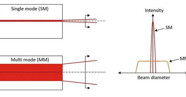
There are two types of fiber lasers, single mode and multi mode. Single mode fiber lasers are typically delivered via fiber with a core diameter of less than 25 microns, producing a narrow, high intensity beam that can be focused down to a spot size as small as 20 microns. This high intensity, small spot is ideally suited for fine laser marking, micro machining, or cutting applications.
Multi-mode (also called higher order mode) fiber lasers, by contrast, use fibers with core diameters greater than 25 microns, resulting in lower intensity beam and larger focused spot sizes. Figure 1 shows graphically the difference between single mode and multi mode lasers. Single mode lasers have the best beam quality laser, with M2 values around 1.1-1.2. Lasers with M2 values above this are considered multi mode (higher order). The fiber laser naturally produces a high quality beam, so on paper the differences may appear small, but they are huge in processing terms.
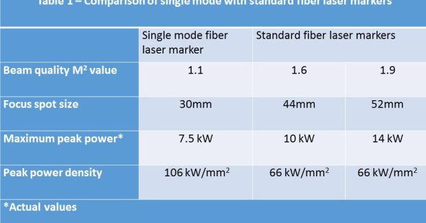
Table 1 compares commercially available fiber laser markers with the single mode fiber laser. For a given optical setup, the single mode laser has the smallest spot size and highest peak power density. Even though the single mode’s maximum peak power is less than the standard laser marker’s, the single mode’s peak power density (which defines process capability) is almost two times higher.
LASER MARKING
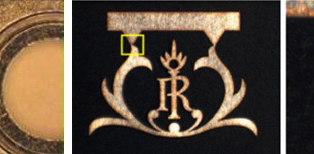
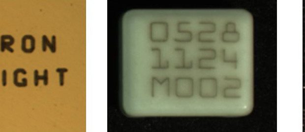
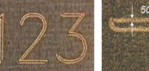
The single mode laser provides excellent mark resolution, and can achieve the mark size and quality normally associated with 532 nm and 355nm lasers. Figure 2 and Figure 3 provide a few illustrations of single mode laser capabilities. In Figure 4, the mark on the left, made in steel with a single mode laser, took less than half the time as the mark on the right, which used a multi mode (higher order) laser using the same optical setup. Figure 5 shows that the single mode fiber laser marker enables finer resolution marking than standard fiber laser markers. It can also provide the same mark resolution, but using a longer focal length optic; for an F theta marking lens, this results in an enlarged working area.
The required mark shown on the figure was 11 in wide, necessitating a 420 mm lens, one of the longest used in regular marking applications. The figure highlights the 50 micron mark line width. The single mode laser was able to use the 420 mm lens to cover the necessary field area, while a standard M2 1.9 fiber laser could only make the required mark using a 254 mm lens. This means that the single mode laser increased the field size by 100 percent!
MICROMACHINING
Micromachining refers to making small features using such standard machining operations as drilling, cutting, scribing and slotting – but on a ‘smaller’ scale. Using single mode fiber laser markers for this purpose can be a cost effective alternative to more costly micromachining technologies, including sinker electrical discharge machining (EDM) equipment, or 532 nm and 355nm Nd:YVO4 lasers.
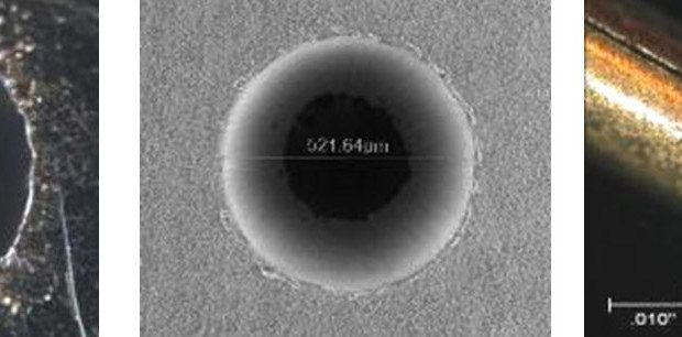
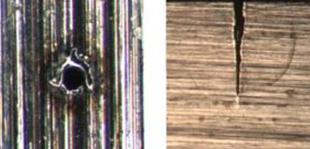
A few examples are shown in Figure 6. The photo on the left shows the use of a single mode fiber laser to drill a 0.008 in diameter micron hole, ±0.0005 in tolerance in 0.008 in thick steel, with no post processing. The center shows a 0.02 in diameter drilled into 0.03 in thick alumina with no micro cracking. The right shows a 0.001 in wide channel cut into a medical tube.
Figure 7 compares the depth and size of holes drilled into steel with a 50 W single mode fiber laser (left) and regular 50 W fiber laser (right) for the same processing time. The single mode laser drills deeper in the same amount of time with a small entry diameter. Figure 8 illustrates the single mode laser’s cut resolution and level of thermal heat input control. On the left, a 0.004 in thick stainless steel metal part is cut from a lead frame. On the right is a 0.015 in copper inlay cut out, showing a close up of the cut resolution and level of thermal heat input control.
The single mode fiber laser marker has best-in-class beam quality that translates to fine marking capabilities, plus effective micromachining for drilling, cutting, scribing, ablation for a variety of applications. This desktop mini marking and machining center can provide both point of use or the benefits of dual or multi-purposing to maximize return on investment. It must be noted that, in additional to having the right tool for the job, it is important to know how to use the tool efficiently and effectively. We have developed a number of machining methods that enable the single mode fiber laser to perform beyond its surface characteristics, while ensuring that process stability meets the requirements of a volume production process.

