Communicate Part Function More Clearly with GD&T
When print tolerances use geometric dimensioning and tolerancing to clearly communicate functional requirements – such as how a hole’s position can vary and still allow for assembly – the tolerances can be made as large as possible without impacting part function.
Posted: February 3, 2016
Geometric dimensioning and tolerancing (GD&T) is a language of symbols that is used on mechanical engineering drawings to efficiently and accurately communicate geometry requirements for associated features on components and assemblies. By clearly and concisely defining a reference coordinate system (datums) on a component or assembly to be used throughout the manufacturing and inspection processes, GD&T dramatically reduces the need for drawing notes to describe complex geometry requirements. GD&T concepts can facilitate and simplify the design of cost saving functional check gages, manufacturing fixtures and jigs.
I’ve had the privilege to be involved in GD&T training over the last year. I am that rare nerd who enjoys this stuff. GD&T is similar to learning Klingon in some ways . . . it makes you feel like an exclusive member of some club that can speak a secret language. GD&T is supposed to be a universal tool, understood by all of those involved in producing mechanical parts: engineering, quoting, manufacturing, inspection and quality. But the problem is that far too many people only learn how to interpret just a few of the symbols that impact their specific job, so they never get an appreciation for the whole system. This is the same as learning a few words in Greek and then trying to read an entire book written in that language. For this reason, many people feel frustrated when they try to use GD&T.
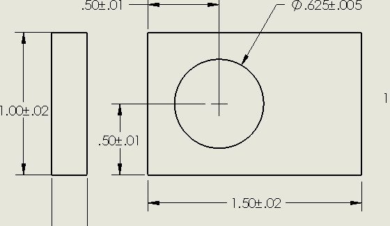
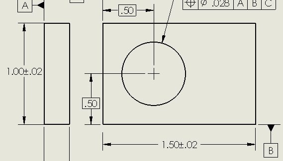
Whenever I teach GD&T, I try to take a step back and give everyone an understanding of why this language is such an important and powerful tool. One big misconception that I often start with is that GD&T is used to specify especially critical features that require super tight tolerances, which implies that any GD&T callout must mean difficult manufacturing and tricky inspections. Notice how the hole position is called out in the two prints in Figure 1 and Figure 2.
Which of these two prints would you rather see in production? Which would you quote lower? Which one will have the most scrap? The plus and minus scheme in Figure 1 looks simple enough. You could teach a new inspector how to interpret these tolerances in less than five minutes. Why would anyone complicate things by making the drawing in Figure 2? Would it surprise you to learn that the tolerance zone is actually larger for the print in Figure 2 without impacting function at all?
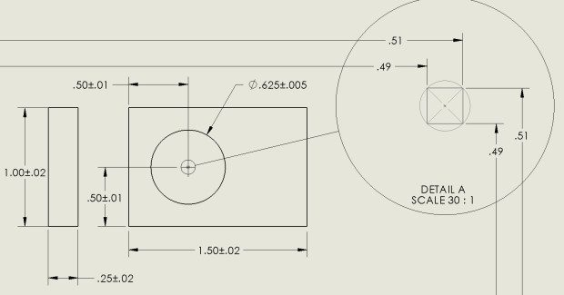
To understand how this can be possible, we need to think about function. GD&T is all about function. What does the part need to do to work correctly? Consider a hole. A hole is round. Just like when we were kids, a round peg usually fits into that round hole. Now consider the function of assembling things with holes and pins or bolts. For things to assemble properly, holes must be within an assigned tolerance that is relative to the location of the bolt patterns being assembled to them. That being said, let’s go back and think about that drawing in Figure 1 again, now shown as Figure 1 with Detail A.
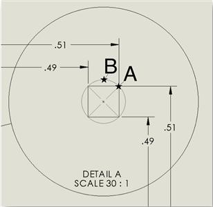
What positions are acceptable for the position of the hole? The plus and minus dimensions allow for a square area or tolerance zone where the center of the hole can be located – from 0.49 to 0.51 in both directions from the edges of the part. What if we were inspecting the position of the center of the hole and its position is 0.510 in both directions, such as position A shown in detail in Detail A?
This would be a good part and, if the engineer did a good job with the tolerances on the drawing, the part should function. But what if the next part we measured had a hole with the center in position B with the dimensions (0.500, 0.528)? This part would be scrap. However, if we think about fitting a round pin in that hole, we can easily imagine that if the part would function with the hole centered at position A, it should also work with that same hole centered at position B. Both holes are the same distance from the nominal hole position of (0.500, 0.500). So, the simple plus and minus tolerance scheme is leading us to reject a part that would function properly – in other words, a good part turned to scrap!
As you probably guessed by now, the GD&T tolerance of position clearly communicates this circular tolerance zone and would accept this functional part. This circular tolerance zone is 57 percent bigger than the original rectangular tolerance zone, without sacrificing any function. Now which print would you rather use? And this is only the beginning, because if we take this a step further and utilize the Maximum Material Modifier on this tolerance, we can add even more tolerance without sacrificing function – but that is a lesson for another time. The important take away here is that when print tolerances clearly communicate functional requirements – such as how a hole’s position can vary and still allow for assembly – the tolerances can be made as large as possible without impacting part function. This is a competitive advantage of using GD&T.
Ron Litke is the engineering manager at Orchid Design, 80 Shelton Technology Center, Shelton, CT 06484, 203-922-0105, Fax: 203-922-0130, www.orchid-orthopedics.com.

