How Close is Close Enough When Trying to Achieve Positioning Accuracy?
Which is better: pneumatic or electric actuation? This review of the various options of each process, along with their advantages and shortcomings depending on application circumstances, can help you make more informed decisions about positioning design and selection.
Posted: August 27, 2016
"The most repeatable method for achieving multiple positions with a pneumatic actuator employs multiple position cylinders. This is the best choice for applications where the discrete stop positions are predetermined and unchanging. When you need more than one stop within the total stroke length, each stopping point must be a “hard stop.” There must be no further travel of the internal piston. And with multiple position cylinders there won’t be, because the piston will impact the end cap at the stopping point."
"By merging pneumatics with electronics, more flexible, nimble positioning control systems have emerged, leading to more efficient, economical use of equipment. The key to this flexibility is the use of a programmable logic controller or other types of electronic controls to create closed loop “intelligence.” Pneumatic actuators may be equipped with either internal or external sensors that deliver a constant analog or digital feedback signal based on the position of the actuator’s rod."
Throughout the years in which we have been developing actuators and an array of motion control devices, we’ve received countless questions from our customers that can’t be quickly answered with glib, off-the-shelf boilerplate language. Some examples include:
- “What can I use to create a repeatable two-stage positioning system with an end-of-stroke hard-stop?”
- “What can I use to create a flexible manufacturing cell that will achieve several different positioning accuracies?”
- “How can I ensure that my electric positioning system does not lose its position accuracy? Is there a component that I can use to prevent this?”
- “Our equipment is controlled pneumatically, but I need a positioning system that can provide extreme and repeatable accuracies. What are my choices?”
- “I have never used an electric actuator for positioning; what do I need to operate it?”
Let’s approach these questions, which share a common concern for positioning accuracy, by discussing some options. Each has advantages and, depending on circumstances, each has shortcomings. With this overview, you will be equipped to make more informed decisions about positioning design and selection.
MULTIPLE POSITION CYLINDERS
The most repeatable method for achieving multiple positions with a pneumatic actuator employs multiple position cylinders. This is the best choice for applications where the discrete stop positions are predetermined and unchanging. When you need more than one stop within the total stroke length, each stopping point must be a “hard stop.” There must be no further travel of the internal piston. And with multiple position cylinders there won’t be, because the piston will impact the end cap at the stopping point.
https://youtu.be/NGWKghY-w0A
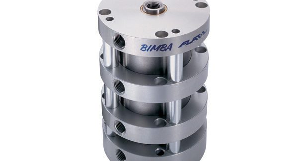
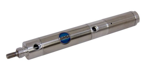
Multiple position cylinders differ from conventional cylinders in that they feature one additional port for each additional position. A three-position cylinder will have three ports, a four-position cylinder will have four, and so on (Figure 1). Imagine one cylinder stacked on top of the other inside the cylinder bodies. A three-position cylinder will have two piston rod assemblies. There will be no mechanical connection between them. By supplying compressed air to one port and allowing it to exit through the other ports, the visible piston rod can be fully retracted and the secondary, internal piston rod assembly will be returned to its home position, fully retracted against the rear end cap. The cycle continues with compressed air supplied to one port and exhausted through another port; the external piston rod assembly will be extended to its partially extended position, and the internal piston rod assembly will make a hard stop at the end of the stroke. And, because this is a hard stop, it will be reproducible.
Multiple position cylinders are an excellent choice for applications where the discrete stop positions are predetermined and unchanging. Their design offers the highest level of repeatability at a relative low cost.
ELECTRO-PNEUMATIC CONTROL
By merging pneumatics with electronics, more flexible, nimble positioning control systems have emerged, leading to more efficient, economical use of equipment. The key to this flexibility is the use of a programmable logic controller or other types of electronic controls to create closed loop “intelligence.” Pneumatic actuators may be equipped with either internal or external sensors that deliver a constant analog or digital feedback signal based on the position of the actuator’s rod. There are two types of internal sensors that run down the inside of the rod:
- A contact sensor, which is a linear resistive transducer with a mechanical wiper attached to the piston. The wiper provides a feedback signal (voltage) based on the position of the actuator’s piston.
- A non-contact sensor, outside of the actuator, senses a magnet attached to the piston inside the cylinder to return a feedback signal (voltage).
The actuator is controlled by a closed loop motion control system, featuring a pneumatic valve capable of receiving and responding to a command signal that monitors the actuator’s position and adjusts the command signal to the actuator to position it accurately.
https://youtu.be/tVe2wP_JRDU
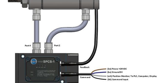
In a closed loop pneumatic system (Figure 2), the valve receives its command signal and supplies air to extend the rod. As the rod moves, the actuator’s sensor provides a continuous feedback voltage to the valve so that the valve continues to supply air on the extend side of the actuator until the feedback voltage equals the command voltage. Conversely, as the command signal (less voltage) is supplied to the valve, it opens flow to the retract side of the actuator to retract it. The valve will supply pressure to either the extend or retract port to maintain the targeted position. Changing the actuator’s stroke length or the velocity with which it operates can be controlled via the electronics. The actuator will extend or retract based upon the voltage it receives and adjust its velocity based upon the speed at which the command signal is sent. Here are the pros and cons of pneumatic motion control:
Pros
- Large load carrying capabilities
- High speed velocities
- Accurate to 0.010 in
- Closed loop control – upstream/downstream communications
- Can be applied to various environments
- Ease of setup
- Medium expense
Cons
- Air supply between valve and cylinder longer than 10’ affects performance
- Compressibility of air can create “overshoot” at faster velocities
- If load requires rigid positioning, additional locking mechanism may be necessary
- Large air leakage creates abnormal valve sequencing to maintain position
ELECTRIC ACTUATORS
For extreme positioning applications that require maximum flexibility, repeatability, and hence, maximum reliability, electric actuators offer the best positioning solution. Two different kinds of motors drive an electric cylinder: stepper motors and servo motors.
https://youtu.be/kKg-JE9q3ms
Steppers are digital input devices that are well-suited for applications in which control signals appear as digital pulses. The digital pulse is a highly reliable means of controlling shaft rotation and thus, the linear motion of the electric actuator. The advanced electronics of the stepper drive produce a clean, reliable pulse train of square waves that arrive at the motor. In contrast, a multi-position actuator can only provide a few discrete positions, and a typical pneumatic electro system with a 10-bit analog resolution is limited to 1,024 discrete positions between the maximum and minimum position. Assuming a 10 in stroke, the electronics can cause, theoretically, a minimum of 0.010 in of change in position as a result of a minimum increment. In practice, however, most electro-pneumatic cylinders provide about 0.1 in of change when external variables such as friction are considered.
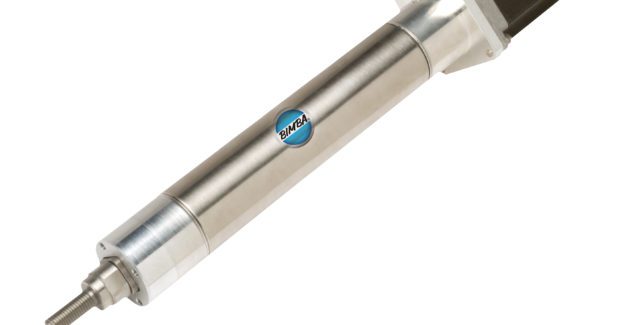
Compare this to the highly precise and well defined motion of an electric actuator, which can easily be controlled to 1/8 in and, in theory, to much less. In other words, an electric solution implementation consisting of a stepper motor (Figure 3) can increase the precision of the positioning application monumentally. Additionally, stepper motors, with their advanced electronics within their drives, inherently provide smoother motion than electro-pneumatic systems. Here are the pros and cons associated with stepper motor positioning:
Pros
- Provides precise positioning accuracy and resolution
- Ideal for positioning high thrust loads at low speeds
- Outstanding repeatability
- Digital input pulses ideal for precise positioning
Cons
- No feedback – could lead to positioning errors
- Load must be static – reduces flexibility
- In case of misstep, continues to try to position
Servo motors are an alternative to stepper motor technology, most useful when the load in the process is inherently dynamic. By definition, a servo motor attached to an electric actuator comes with feedback. This feedback produces an additional layer of protection to ensure that the position of your electric actuator is accurate, reliable, and repeatable. This is because the amount of error that is tolerable can be precisely configured by the operator via the servo drive. This tolerable error can be better refined to match the level of positioning required by manipulating the maximum error in encoder counts. So, one can achieve a very fine positioning accuracy using a servo motor. Here are some servo motor positioning advantages:
- Position feedback
- Positioning error configurable – tighter positioning tolerance
- Adapts to changing loads
- Capable of short bursts of peak current to improve positioning
- Faster positioning even with larger loads
SUMMARY
There are many ways to achieve positioning functionality using both pneumatic and electric actuators, from pneumatic multi-position cylinders to pneumatic electro-systems, to electric cylinders with step motors, to electric cylinders with servo motors. The best positioning solution is always dependent on the individual application and the level of positioning accuracy and repeatability one is attempting to accomplish. Other considerations include cost, complexity, load, speed, precision, location, and similar variables. Some applications can perform and thrive using multi-position cylinders. Others require the feedback and the robustness of the electro pneumatic system, while still others require the enhanced precision, programmability, and repeatability found in electric actuators.
No matter what your particular positioning application may call for, the first step in selecting a positioning cylinder solution is to choose a reputable cylinder manufacturer that understands and makes available all the various positioning technologies and is able to recommend a solution that best meets the overall needs of the application.
Jerry Scherzinger and Gilbert Guajardo are product marketing managers for pneumatics at Bimba Manufacturing Company, 25150 South Governors Highway, University Park, IL 60484, 708-534-8544, Fax: 708-235-2014, www.bimba.com.


