Getting the Edge You Need When Beveling
Beveling is an integral part of joining components. There are many ways to create a beveled edge, and the method or tool you choose makes a big difference in completing the operation quickly, reliably and safely. To help you in this selection, let’s take a closer look the beveling process, which is still considered by many to be as much of an art as a science.
Posted: October 7, 2016
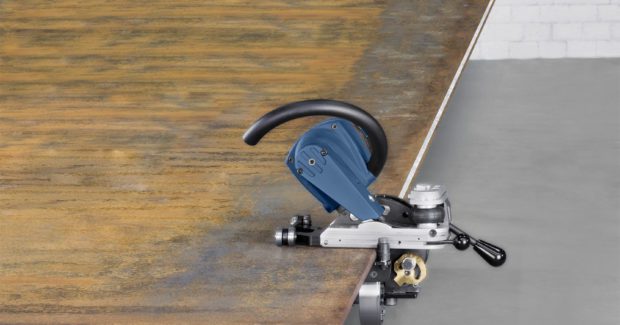
Creating a perfect beveled edge for weld preparation can be a challenge. In fact, many people consider it as much of an art as a science. The beveling process itself is quite simple: an angled slope is cut on the edge of a piece of metal to prepare the material to receive a welded seam. It is a very common procedure yet one that comes with much variation. There are several ways including flame cutting, grinding or a nibbling operation that will achieve a beveled edge, but to find the best or the most effective approach requires a look at your application and where the bevel occurs.
DEFINING THE BEVEL
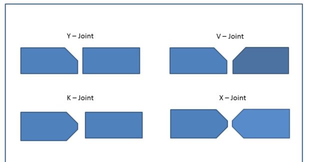
When attempting to bevel the best edge, first remember that the welding joint configuration, typically identified as a “V”, “double V”, “K”, or “Y” shape joint, will influence the degree of the bevel placed on the material. For example, the standard slope when beveling pipe is typically 37.5 deg while the standard for beveling flat sheet is 45 deg. Regardless of the angle taken and the length of the beveled edge, the most important objective is to keep the angle within the tolerance level of the application. This will help to achieve a high quality beveled edge – and this is vital to the weld. An incomplete or poorly produced bevel will negatively impact the strength and the integrity of the weld.
Most industries have standard procedures in place to help ensure the metal is prepared and welded correctly based on these concerns. In the welding industry, where structural integrity is of the utmost importance, the weld will be subject to inspections and failure assessments. While aesthetics tend to be of a lesser concern, fabricators with a highly visible end product, such as those manufacturing parts for the food industry, will be at least somewhat concerned with the how the final part appears.
TWO MAIN CHALLENGES
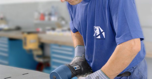
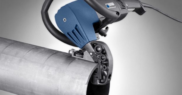
With an understanding of the application, it is important to understand the two areas that typically present the biggest challenges in weld preparation. The first is the shape and location of the edge that will be beveled. Beveled edges can be created on a straight flat edge, curved surface, an inside radius or on the diameter of a pipe. Curved edges or inside cutouts are particularly challenging due to the limited access a beveller has to the edge. It is nearly impossible to cut tight corners consistently by flame cutting or grinding. Instead, a handheld tool with adjustable settings tends to be the most flexible as they enable users to achieve a full range of motion in any direction in the safest and most efficient way possible. The challenge of a straight edge can be its length, which typically ranges from 0.25 in to 6 in. The longer the edge, the more difficult it is to keep the tolerance throughout the application.
The second common area of concern relates to the type of material being processed. When working with mild steel, for example, beveling is often achieved by flame cutting. This causes an oxide layer to form on the edge of the material which must be removed prior to the welding process. While this flakey layer is easy to remove manually, the additional processing step will add time to the job. High strength steels (HSS) also present a unique challenge due to their extremely hard composition. Many tools cannot bevel a HSS edge at all, and those cutting tools which are able to bevel HSS tend to wear very quickly. As a highly malleable material, aluminum is much easier to process than high strength steels, yet the various grades of the material are each associated with their own difficulties in processing.
HEAT, CONSUMABLES AND OTHER CONSIDERATIONS
While completing the job is the first priority, factors such as the cost of operation, the speed and flexibility and the safety of the tool or process should also be a concern. When metal is produced, different alloys such as chromium, magnesium or iron are combined in varying levels to achieve the required structural characteristics. The material is delivered to the user with known characteristics, but if heat is applied, for example through flame cutting or grinding, the micro-structural characteristics of that alloy composition can change. This can have a residual effect and is the reason why the “heat-affected zone” is often mentioned in welding specifications. Even when the HAZ is not an issue for the application, heating the material may release unhealthy fumes under the right conditions – an important factor for the overall well-being of employees.
Once the application and material challenges are met, it is time to think about the consumables required by each beveling method. Sharp cutting tools, grinding wheels, cutting gases, nozzles, and other consumables are required to guarantee consistent quality and to complete a job without interruption. Consider how often they wear or need to be replaced and how difficult the job might be to make the switch. If the tool is used quite frequently or on a job site, consumables might be a significant deciding factor in your purchase. The weight and mobility of the tool will also play a role when it comes time to bevel a part. If the operator is able to run the tool alone and without fatigue for an extended period of time, productivity will remain high. Other benefits, such as an automatic feed option or solutions to quickly adjust the degree of the bevel or set up the tool, will further increase cycle time and reduce costs. They also tend to create a better work environment for the operator.
Beveling is an integral part of joining components across a diverse range of applications and industries. Although there are many ways to create a beveled edge, the method or tool you choose can make a big difference when it comes to completing the operation quickly, reliably and safely.


