Simulate Welding of Larger and More Complex Components
Ideal for aerospace, automotive, shipbuilding, plant engineering and machine construction, Simufact Welding 6 from MSC Software quickly simulates longer welding seams and multiple welding points for arc welding, spot welding, brazing and stress relief, electron beam welding and laser beam welding.
Posted: December 21, 2016
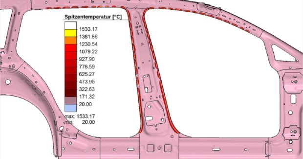
Simufact Engineering GmbH (Hamburg, Germany), which is part of MSC Software Corporation (Newport Beach, CA), has launched Simufact® Welding 6, an advanced version of their welding simulation solution. One of the most important novelties in this new simulation software is the addition of simplified calculation methods that allow significantly shorter calculation times for thermal and thermal-mechanical welding processes. This paves the way for the simulation of longer welding seams, multiple welding points and larger, more complex assemblies to be calculated within a practical simulation time. Through continuous development of the solver – the ‘calculation core’ of the software – users can now considerably shorten simulation times while being assured of an increased computational stability.
Simufact Welding 6 covers a wider range of applications for the simulation of joining processes. It differentiates between the methods of electron beam welding and laser beam welding, and expands the arc welding and resistance spot welding processes to cover brazing and stress-relief heat treatment. Within the aerospace, automotive, shipbuilding, plant engineering and machine construction industries, large complex assemblies are often created during production with, for example, meter-long welding seams and multiple welding points. Because a large number of physical effects must be taken into account, simulating such joining processes with fully-transient calculation methods involves a long computation time to produce a highly accurate simulation result.
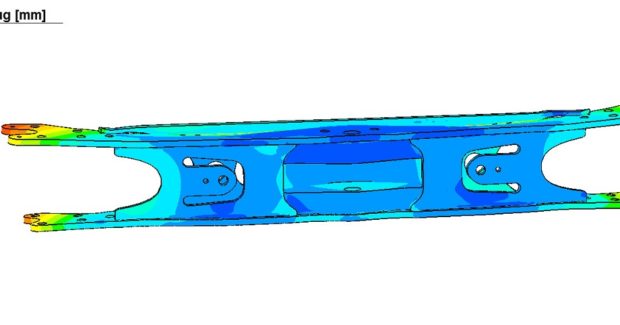
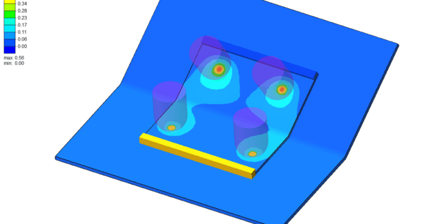
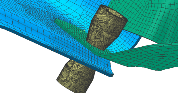
When questions of feasibility or trend statements arise, Simufact Welding 6 serves as a reliable tool to provide statements, for example, on distortions and residual stresses of complex structures within practical short calculation times. The welding simulation software is also scalable: besides the well-known, high-precision calculation methods already used, it now offers simplified calculation methods that can quickly provide statements on distortion directions during thermal and thermal-mechanical joining processes, such as resistance spot welding. These simplified simulation methods enable designers to examine their models with regards to production issues. Such a ‘model check’ helps the users to adapt their models according to the simulation result and optimize them prior to production.
Simufact Welding 6 expands the range of process types that can be simulated to include brazing and stress relief, as well as differentiating between electron beam welding and laser beam welding methods. All of these new process types are added to the arc welding and resistance spot welding processes that are already available in the software. Brazing simulations are used to predict distortions and stresses during brazing processes that typically employ heat sources with lower heat input (compared to welding processes), often limiting the heat input to soldering material. The Brazing application module lets the user limit the heat input to the filler material during a standard brazing process. Users who work with laser brazing processes can also apply the heat source to the whole model.
The ‘Stress Relief’ module simulates stress relief heat treatment after welding, a common post-processing step used to reduce residual stresses within the workpiece. The ‘Electron Beam’ module provides functional improvements that allow the welding process to be modeled in a vacuum chamber so that the user can calculate the heat loss before and after welding. Post-Particle Tracking and THS plots help the user to evaluate their simulation results. Post-Particle tracking allows the user to customize the measuring point settings that are used for a comparison of the simulation results with the measurement data, ultimately making the simulation model and its results much easier and faster to evaluate and optimize. During the welding process, the engineer can measure and evaluate the forces on the clamping tools with the help of the Time History Plot function. The measurements given by this function provide information about forces experienced by clamping tools, tool displacement and other important data for optimizing the clamping devices.
Future software improvements will include a revision of the heat sources, flexible temperature objects, a complete revision of the time step control system, a CAD import function for tools and a comprehensive revision of the modeling process and the results management system regarding the preview functions, revised color coding, UNV export function, heat source database and assemblies among other features.
MSC Software Corporation, 4675 MacArthur Court, Newport Beach, CA 92660, 714-540-8900, www.simufact.com.


