Trends in Hydraulic Clamping Systems for the Press Brake
Depending on the press brake and setups, there are a number of hydraulic clamping options that fabricators can use to work within their budgets and production requirements. From a fully modular hydraulic clamping system or by retrofitting safety tangs onto straight-tanged punch tools, streamlining production with hydraulic clamping solutions can deliver greater efficiencies in your shop and help you compete with the world.
Posted: February 20, 2017
Faster setups. Higher quality parts. More streamlined production. When it comes to metal fabrication, production and job shops alike need greater efficiencies on the shop floor to compete within the global marketplace. Press brake clamping systems in particular were designed to help address the need for greater efficiencies, yet many clamping systems simply couldn’t hold up to the rigors of production. Before the first hydraulic clamping systems became available, time-consuming setups plagued sheet metal fabricators. Manually loading punches and securing multiple setscrews for each job changeover accounted for significant downtime in the shop. Hydraulic clamping systems allowed operators to simply load the tools in the press brake and hit a button that clamped and seated the entire setup.
While these clamping systems gave manufacturers significantly faster setups, the first systems presented a number of flaws and challenges. Durability, lead time and overall quality of the systems simply couldn’t withstand the rigors of many production facilities. That’s when tooling manufacturers decided to develop new systems that could offer sheet metal fabricators a more durable solution and a faster lead time.
RUPTURED BLADDERS AND DAMAGED BEAMS
Two of the largest headaches fabricators experienced with the first hydraulic clamping systems were urethane bladders rupturing and premature worn surfaces. Inside the clamping system is a urethane bladder filled with hydraulic fluid. As the fluid expands the bladder pushes on a pin inside the beam that secures the tang of the punch or die. Because the bladder expands and contracts repeatedly throughout the press brake operation, this action caused considerable wear on the bladder itself. After a period of time, the bladders would rupture, making a mess of hydraulic fluid and causing significant downtime for maintenance in the shop.
Worn beams also created challenges for fabricators because of durability concerns: the hydraulic clamping systems simply weren’t up to the task of rigorous production demands. Beams often showed signs of wear within months after purchase and tooling manufacturers were hearing from fabricators that the beams in the clamping systems simply weren’t lasting long enough to be worth the investment. Problems such as weak bladders and worn beams caused significant downtime and added maintenance costs for manufacturers – exactly what fabricators were trying to get rid of. Because the beams were one long continuous part, there was no way to segment the beam damage so any damaged area of the beam required fabricators to replace the entire component. An additional downside was tooling manufacturers couldn’t make the systems fast enough to keep up with demand for new and replacement clamping systems.
IMPROVED HYDRAULIC CLAMPING SYSTEMS
With issues of quality, dependability and delivery as core problems being faced by the industry, tooling manufacturers sought to make more durable versions with an overall higher quality that could be delivered to fabricators within a much faster lead time. Two hydraulic clamping solutions that came out of the effort included the ExpressRail and ExpressRail 2000. After significant research, testing and development, these hydraulic two clamping systems offered a bladder made from an improved urethane composite that could better withstand the stresses of press brake clamping operations. Engineers working on the new hydraulic clamping systems developed beams made with a through-hard material. Few of the previous systems were hardened at all, which accounted for much of the damage during operation. With the new beams, fabricators could expect longer beam life with a hardened material.
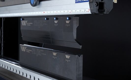
ExpressRail was the first system developed to combat the quality, dependability and delivery challenges that existed in the field. The system brought not only a stronger hydraulic fluid bladder and hardened beam, but delivered a modular beam system to hydraulic clamping operations. The operator is the most powerful component to any press brake and human error can find a way to damage even the best quality tooling and machines. In the cases when damage occurs when using a modular system, sections that needed replacing could be replaced, and those that didn’t get damaged could be salvaged. This feature can save fabricators a great deal of time and money.
For example, if the clamping system consisted of five two-foot sections and one or two of those sections were damaged, the manufacturer could still salvage three or four of those sections. With the older, non-modular systems, if any part of the beam was damaged, the entire beam would need to be replaced, as there would be no way to salvage any undamaged area of the beam.
The ExpressRail 2000 came out shortly following the ExpressRail to offer manufacturers a more cost-effective option. While the 2000 features the improved and more durable bladder and hardened beam, the beam is one piece and not a modular option. The hardened beam on the 2000 model is through-hardened and registers a 28 RCS to 32 RCS (Rockwell C scale). Each of the beams on the modular version, the ExpressRail, is further heat treated with a proprietary process to 70 RCS, which delivers an even greater level of hardness.
SAFETY AND POWER
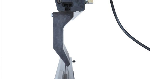
The number one safety consideration when working with hydraulic clamping systems is making sure the punch has a safety tang. While many sheet metal fabricators use old-fashioned or planer milled punches without a safety tang, the hydraulic clamping does not feature redundancy in ensuring the punch stays clamped during a power loss situation or simply during changeover. Safety tangs come in the forms of buttons that allow the tang to retract, solid material that creates a hook or little tabs on top of the punch. Punches can and should be retrofitted with a safety tang prior to using in a hydraulic clamping system for the sole purpose of safety.
As well as a safety tang, punches that offer a self-seating feature are recommended for use in many types of hydraulic clamping systems. Not all types of clamping systems are compatible with self-seating punches; however, those that are use G-style or Groove-style tooling. The self-seating feature of this type of punch design provides a setup that simultaneously seats and clamps the punches. G-style tools are designed with small notches on either side of the punch tang. A series of pins are pushed into the groove and pulls the punch upward and fully seats it into the upper part of the clamp. This feature is an added time saver when setting up tooling since the seating process is no longer necessary.
When implementing a hydraulic clamping system there are two choices for controlling the system: using a standalone pump or integrating into the machine control and hydraulic system. It’s important to be aware that the selected power source may disrupt the clamps if a power failure should occur. Assessing the power source is an important consideration. If the hydraulic power source features a one-way valve that holds the power supply, then the clamping system will retain a secure grip on the punches. On the other hand, if the power supply does not feature a one-way valve, when a power loss occurs and the fluid falls away, then the system would unclamp and the punches would fall (this won’t happen if you have the proper safety tangs as suggested), causing significant damage to the tooling and the press brake, and putting operators at risk of injury.
MAXIMIZING ROI
The most valuable return on investment for manufacturers is the time and labor saved by implementing any type of hydraulic clamping system. The time between the last good part and the first good part is the definition of a setup time. Comparing the time involved to use setscrews or bolts for upper and lower clamp plates in a 4 ft setup verses using a hydraulic clamping system would most likely cut the setup time by a third. As the length of tool setup becomes longer the savings becomes greater. Manual systems require operators to determine if tooling is secure with no great visual indicators. If bending begins and tooling is not secure as thought, damage and danger to the operator can occur. With hydraulic clamping systems, the punches are either clamped or not and usually there is a visual indictor to show if the clamping is engaged or not, thus eliminating the guesswork that is inherent when working with setscrews and bolts.
Further cost savings occur in the choice of a modular hydraulic clamping system over a non-modular system. While modular systems come at a higher price point up front, they can save manufacturers time and production costs in the long run because the design offers a more durable system which will reduce maintenance costs and the modular sections of the beam can be replaced or repaired without having to replace the entire beam. Depending on the press brake and setups, there are a number of hydraulic clamping options fabricators can implement that will work within their budgets and production requirements. Whether that’s implementing a fully modular hydraulic clamping system or retrofitting safety tangs onto straight-tanged punch tools, streamlining production with hydraulic clamping solutions can help deliver greater efficiencies in your shop that will help you compete with the world.


