Seven Tips for Inert Gas Weld Purging of Pipes
Effective weld purging can only be achieved by making sure that any residual oxygen is displaced from the purge zone prior to and during welding to prevent significant loss of corrosion resistance and a reduction in joint strength. Here are some insights on how to properly conduct and monitor this process to ensure compliance.
Posted: July 14, 2017
Weld purging is the act of removing oxygen within the vicinity of a joint before, during and after welding, especially when joining metals such as stainless steel, titanium and zirconium. Effective weld purging is only achieved by making sure that oxygen is displaced from the purge zone prior to and during welding. Any residual oxygen can cause significant loss of corrosion resistance and a reduction in joint strength. It is therefore essential to seal the pipe on either side of the joint and maintain this seal throughout the process. The residual level of oxygen in the purge zone needs to be consistent with the welding procedure so continuously monitoring to ensure compliance is crucial. Here are seven tips to help you in the inert gas weld purging of pipes.
1. CHOOSE A DEPENDABLE SEALING MATERIAL
The cheapest is seldom the best, so examine the options available. Don’t be tempted to use sealing discs made from polystyrene foam, wood and cardboard: at best, they leak or emit contaminants and at worst they catch fire during the hot weld cycle (see Figure 1).
2. USE A COMPLETE PURGING SYSTEM
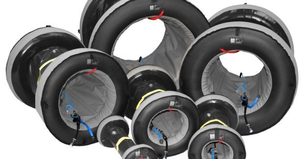
Don’t try to economize by making use of whatever happens to be around at the time. Separate seals for the pipe and rubber tubing for the inert gas, all held together with bits of tape, seldom succeeds. Invariably this is time consuming and can only be used once. Find systems using inflatable dams. Commercial equipment is now available in which gas flow and pressure and purge gas quality are all pre-set. Complete monitoring instrumentation can be incorporated to ensure a high level of quality control. These systems have been designed for multiple use and are rugged enough to cope with site conditions while still reducing overall purging and welding time very significantly (see Figure 2).
3. ESTABLISH WHAT LEVEL OF OXYGEN IN THE PURGE GAS IS ACCEPTABLE
There is plenty of published information available that establishes what the maximum oxygen content needs to be to prevent loss of mechanical and physical properties in the weld. This depends on the material being welded, but generally some stainless steel welding requires a low level, whereas most carbon steels are much less sensitive.
4. TAKE CARE WITH GAS FLOW
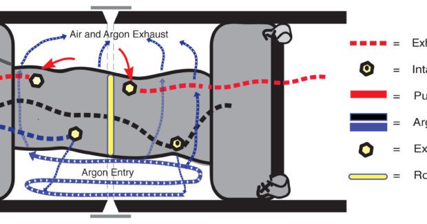
Whatever system is selected, ensure that the inert gas enters gas slowly. Argon is heavier than air, so introduce it slowly at the bottom of the weld purge space and discharge from the highest point. Helium is lighter than air and needs to be inserted at the top of a cavity and removed at the base (see Figure 3)
5. DON’T RUSH INTO THE WELDING SEQUENCE
Wait until all the air has been displaced before welding. For many metals this means ensuring a residual oxygen level below 100 ppm. Traditionally this is based a pure guesswork – a practice still followed, even by major metal fabricators. If the oxygen content is too high or varies during welding, oxidation occurs and this often means rejection with the expense of re-machining, and therefore production delays. It can also lead to loss of corrosion resistance in stainless steels.
6. USE A PURGE GAS OXYGEN MONITOR
Don’t assume that allowing “plenty of time” for purging will remove all the oxygen. If there are leaks in the system, turbulence or simply poor quality, purge gas then oxygen levels could be way above those necessary to prevent contamination. The best solution is to use a device capable of accurate and reliable measurement of oxygen level (see Figure 4).
7. READ PUBLISHED INFORMATION ABOUT PURGING
There’s plenty of published material and examples are listed below. Learn from the experience of others rather than using trial-and-error methods that could cost time and necessitate re-welding.
References
1. Argweld products from www.huntingdonfusion.com.
2. Developments in Weld Purge Gas Oxygen Monitoring Technology, Stainless Steel World, March 2015.
3. Guide to Weld Discoloration Levels in Stainless Steel, American Welding Society, AWS D18.2:1999.
4. Choosing an Effective Weld Purging Technique, Stainless Steel World, May 2013.
5. Danger of Corrosion when Welding Stainless Steel, Food Safety Magazine Digest, November 2014, www.foodsafetymagazine.com.
6. Major Advances in Weld Purge Technology, World Pipelines, 2014.
7. Latest Developments in Weld Purging, www.energyglobal.com.

