Best Practices for Optimizing Reamers
Using a reamer can extend gun and consumable life, reduce downtime and labor costs for component changeover, improve weld quality and reduce rework, and help shorten the return on investment in a robotic welding system. To achieve these benefits and more, here are some of the reamer best practices to follow.
Posted: February 7, 2018
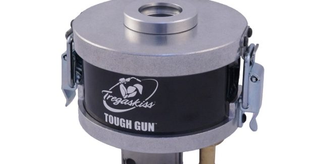
Maximizing performance in an automated welding system involves many factors, from choosing the right equipment to proper cell layout. Integrating peripherals into the system is another step that operations can take to boost performance and results. A reamer, also called a nozzle cleaning station, removes spatter from inside the front-end consumables of a robotic MIG gun. Because spatter accumulates in nozzles and on contact tips and retaining heads during routine welding, utilizing a reamer can extend consumable life and reduce downtime for maintenance, in addition to preventing loss of shielding gas coverage that could lead to porosity issues. These benefits can impact the operation’s bottom line through reduced rework and improved weld quality and productivity in robotic weld cells. To optimize your system’s performance, quality and equipment longevity, consider the following reamer best practices:
REAMER BASICS
Cleaning a gun’s front end by hand takes significantly more time and resources than completing the task with a reamer. A reamer can typically complete a cleaning cycle in five to six seconds during welding process downtime when tooling is indexing or parts are cycling down the line. By comparison, it can take more than five minutes for an operator to stop production, enter the weld cell and do this cleaning manually. A reamer also delivers quality benefits by ensuring proper shielding gas coverage to protect the weld pool and by greatly reducing the risk of spatter bridging between the contact tip or retaining head and nozzle, which can lead to arcing against the part. When choosing a reamer, consider the two different types:
- Analog reamers typically have an air supply and a multi-conductor cordset. Each conductor relays a specific task, including a start signal, a spray signal, a home signal and others. The function of those leads directly control the reamer’s actions via the circuit board.
- Digital reamers use an Ethernet network cable to send commands to an IP address, providing the ability to control individual functions without being limited to the number of leads in the cordset. A digital reamer can be programmed for all the functions of a ream cycle, including start, spray, clamp, lift, lower and turning the motor on and off. Remote monitoring is another option with digital reamers that can reduce the time spent troubleshooting problems.
INSTALLATION AND SETUP
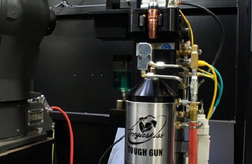
A reamer should be placed close to the welding robot so that it’s easily accessible when needed. As long as the reamer doesn’t allow the clamp housing to collect debris, it can be mounted in nearly any desired orientation. If the reamer is placed at an angle and anti-spatter spray is present, some provisions should be made to avoid leakage when the spray reserve is full. In these situations, consider using a multi-feed system that connects a hose to the main source of anti-spatter compound, which operates the same regardless of reamer orientation.
https://youtu.be/f0DgVx2oGCM
GUN ALIGNMENT WITH THE CUTTING BLADE
Check these factors to help ensure optimal cleaning:
- The V-block inside the top of the reamer is the correct size for the nozzle.
- The cutter blade is the correct size for the nozzle bore.
- There is adequate insertion depth of the nozzle to the reamer.
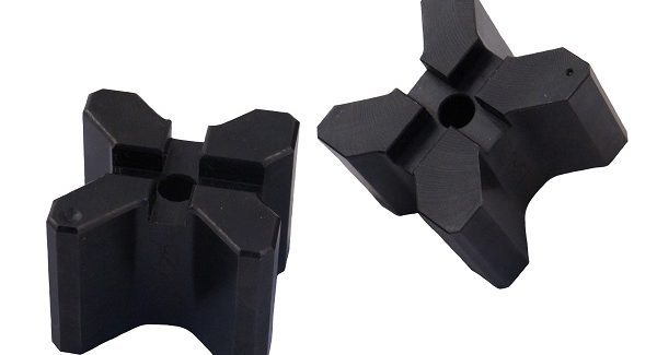
A V-block that is the appropriate size will allow the nozzle to sit tangent on the two angled faces of the V-block. The two faces of the V-block and the two faces on the reamer hold the nozzle in place using four points of contact. This ensures proper alignment over the cutter blade during cleaning. When a nozzle size change is required for an application, be sure to index the V-block to the proper side to keep the nozzle concentric. A V-block that is the wrong size for the nozzle causes off-center positioning, which results in the cutter crashing into the nozzle when it advances for the reaming cycle. The cutter blade should reach the gas holes without interfering with the retaining head. When reamers are positioned to reach too deep, this causes the cutter blade to push the gun upward, potentially forcing the nozzle off the retaining head.
PROPER USE OF ANTI-SPATTER SPRAY
Anti-spatter compound can be used with reamers to enhance performance. For optimal spray coverage, follow the manufacturer’s chart for proper setup based on nozzle bore size. Spraying too far from the nozzle results in inadequate coverage, while spraying too close can lead to the nozzle insulator becoming saturated, which can cause premature nozzle failure. Recommended spraying time is about a half second. If there is a need to spray longer, it likely means the sprayer is too far away, which can also create a mess in the weld cell. Proper positioning helps ensure the anti-spatter is applied to the part, rather than blown into the air. A spray containment unit can also capture excess anti-spatter and ensure proper positioning of the torch while spraying to help keep the weld cell clean.
PREVENTIVE MAINTENANCE
To keep a reamer running optimally for longer, regular maintenance is key. Take time to clean away debris buildup on the V-block and jaws, which can push the nozzle out of position and lead to loss of concentric fit-up and possibly broken cutter blades. Keep clamp faces clean by scraping the V-block faces to remove debris. It’s also important to clean the top seal on the spindle under the cutter. Excess spatter or debris buildup here can score the spindle shaft, leading to premature spindle failure. Adding an air blast feature to the gun can also support reamer function. This feature blows high-pressure air through the gun’s front end to remove debris and contaminants. Air blast can reduce the necessary frequency of reaming, saving time in the production process.
BENEFITS OF REAMING
Reamers provide many benefits that can help shorten the return on investment in a robotic welding system. Using a reamer can extend gun and consumable life, reduce downtime and labor costs for component changeover, and improve weld quality and reduce rework.


