Processes for Welding Tanks and Pressure Vessels
Using the best possible pressure vessel welding process is critical for durable welds that are free from defects. What is the best process for pressure vessel fabrication? Here is a closer look at many of the potential factors to consider.
Posted: February 13, 2018
The tank and pressure vessel market is worth $11 billion in the U.S. alone. From food processing and fermentation through to nuclear waste storage and pharmaceutical processing, vessels are used in a myriad of industries to both store and transfer liquids and gases under high pressure. Given the critical nature of pressure vessels, the welds used in their fabrication undergo a rigorous quality control and assurance process, including X-ray inspections, ultrasonic testing and a variety of other forms of non-destructive testing (NDT). If a pressure vessel weld fails to meet these quality control and assurance processes and non-destructive testing, the reflection of the defective weld can be both difficult and expensive to rectify.
As such, the use of the best possible pressure vessel welding process is critical: it improves the likelihood of a durable weld, free from defects such as porosity and inclusions. This, in turn, helps welding workshops deliver profitable projects and secure repeat business. So then, what is the best (highest productivity and highest quality) process for pressure vessel fabrication? This is a very broad question, with many potential factors influencing the answer. The most important considerations (each of which is outlined in more detail below) include:
- What Code or Client Specifications must be met? The first factor to consider is likely to be the code, or customer specifications that must be met. The specifications may dictate which welding processes are allowed, which processes are not suitable, and any preparation required, as well as the type of testing required to validate the quality, strength and durability of the welds. Based on these specifications, you may need to draft a new set of job-specific Procedure Qualification Records (PQRs). It is at this point that you may also need to offer your expertise to your customer, recommending the most suitable material for their needs, based on criteria such as corrosion resistance, durability for heating and cooling cycles, and the required working pressure of the contents.
- What type and how thick is the material being welded? The second factor to consider when selecting an option for the welding of pressure vessels is the type of materials that need to be welded. You should consider these questions:
- If the material is corrosion resistant, can I effectively keep it separated from any carbon steel work?
- Do I have the equipment to form the bodies of the vessels in the thickness specified?
- What is the optimum welding process for this material?
- How do I make that welding process as efficient as possible?
- Do I need to use a multi-process approach to achieve the greatest possible efficiency?
- Can I automate the welding process for consistency and speed?
- What is the lead time of the project?
- How many tanks or vessels need to be welded and over what time frame? The third factor to consider is the number of tanks or vessels to be welded, whether this is a one-off project or continuous production, and what is the time frame for delivery. Armed with this, you’re then in a position to consider:
- What welding process will deliver the best quality?
- What welding process will deliver the most consistency?
- What welding process will deliver the fastest results?
- What combination of the above, if any, is ideal?
- What parts of the job can be welded with automation?
COMMON PROCESSES FOR WELDING TANKS & PRESSURE VESSELS
Once you have taken the three factors outlined above into consideration, you will generally be left with three main processes to consider for welding tanks and pressure vessels:
- GTAW. Conventional TIG/GTAW is a melt-in process that typically results in a broad, shallow weld pool. Conventional TIG tends to be restricted to currents below 250 amps because higher amperage (resulting high arc pressure) depresses the weld pool surface and creates an unstable, turbulent weld pool. The practical upper limit for single pass GTAW welding is generally considered to be 2 mm. Beyond this thickness, a V-groove root pass is normally applied, followed by filler passes. Machined groove preparation is preferred for the sake of process consistency, which adds cost, and the removed joint metal must be replaced with filler metal. Manually beveled joints often lead to inconsistent welding results. The low energy density arc has limited penetration capability, and the root and fill passes are performed at a slow travel speed, typically resulting in many weld passes and lengthy welding times.
- Plasma Welding. This is the most complex of the arc welding processes. It is extremely sensitive, with precise levels of plasma and shield gases required to form a plasma jet and protect the orifice. This requires meticulous set-up and frequent maintenance. Plasma welding requires highly trained operators to configure and monitor the many parameters, maintain the system and ensure frequent electrode changes. The practical upper limit for single pass PAW welding is generally considered to be 8 mm to 10 mm, although it is more commonly used for root passes of 4 mm to 6 mm, followed by filler passes using TIG/GTAW.
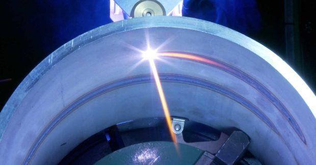
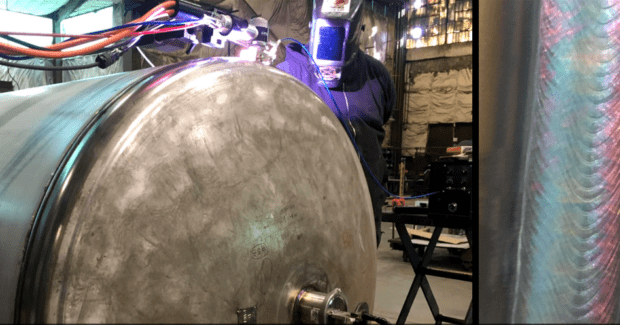
- K-TIG. A high energy density variant of GTAW, K-TIG (Keyhole TIG) is a high speed, single pass, full penetration welding technology that welds up to 100 times faster than TIG welding in materials up to 5/8 in (16 mm) thick, and typically operates at twice the speed of plasma welding. This process works across a wide range of applications, and is particularly well suited to lower conductivity materials such as stainless steels, nickel alloys, titanium alloys and most corrosion resistant and exotic materials. It performs longitudinal and circumferential welds on pipe, plate, spooling, vessel, tank and other applications in a single pass:
- Titanium up to 5/8 in (16 mm) thick
- Stainless steel up to ½ in (13 mm) thick
- Nickel alloys and super alloys up to ½ in (13 mm) thick
- High quality carbon steel up to ¼ in (6 mm) thick
MORE CONSIDERATIONS OF KEYHOLE TIG
The extremely fast welding times of K-TIG result in dramatic reductions in labor costs, welding cycle times, rework and repair costs, gas and power usage. Its single pass, full penetration welds significantly reduce or eliminate grinding and reworking. The process dramatically reduces or eliminates the need for wire, eliminates edge beveling and requires only a square butt joint, but it can also weld into all standard GTAW preparations. No root gap is required. This highly refined version of the TIG/GTAW process was developed by the Australian Government’s Commonwealth Science & Industrial Research Organization (CSIRO; Canberra, Australia) and has been quietly adopted by some of the world’s most productive fabricators and largest vessel fabricators.
K-TIG has 8X the penetration of GTAW, allowing it to perform X-ray quality welds in materials up to 5/8 in (16 mm) thick in a single pass without the need for edge beveling. The resulting welds are performed at up to 100X the speed of conventional TIG/GTAW. Gas consumption is reduced by more than 90 percent and wire consumption is reduced by up to 90 percent or eliminated entirely. The physics of this process create high energy density in the welding arc, allowing it to open up a ‘keyhole’ and fully penetrate the material being welded and weld at high speed. The minimization of the surface energy associated with the keyhole geometry and the relatively unrestricted egress of the arc gases combine to produce an extremely stable and benign weld pool. The molten metal within the weld pool is prevented from falling from the root face by surface tension created by the process.
If you’re using plasma welding to fabricate stainless steel, duplex or super duplex of 3 mm to 13 mm (1/8 in to 13/32 in), it is highly likely that you could benefit significantly from adopting this process. It is likely that you will have already invested in automation equipment to provide a consistent travel speed: typically a positioner, rotator, seamer or column and boom. Your application is probably pressure vessels, suction vessels, cryogenics or tanks. You are probably performing a longitudinal seam weld followed by two circumferential welds, and experiencing unacceptable defect rates and are struggling with thicker materials.
In contrast to plasma welding, the K-TIG process is simple to operate. The arc structure and keyhole develop spontaneously and are maintained automatically by the controller throughout the weld. There is no plasma nozzle or orifice, no precise electrode alignment is required, only one welding gas is used, flow rate is not critical, and the torches are very robust.
Keyhole TIG Ltd., Building 5, 9 William Street, Mile End, Adelaide, SA 5031 Australia, +61 8 7324 6800, www.k-tig.com.
Subscribe to learn the latest in manufacturing.


