Four Tips for Ensuring Proper Shielding Gas Coverage in TIG Welding
You’ve got a job that demands high weld quality and appearance. TIG welding will provide you with a greater level of control to achieve those desired results, but don’t overlook the importance of using the correct shielding gas.
Posted: August 16, 2018
Many welding operations turn to gas tungsten arc welding (GTAW) when high weld quality and appearance are critical to the application. Also known as TIG welding, this process provides the welder with a greater level of control that helps achieve the desired results. One factor that plays a significant role in TIG welding success is proper shielding gas coverage. In this column, let’s discuss four key considerations to ensure you have the proper shielding gas coverage to help optimize TIG welding results:
TIP NO. 1: CHOOSE THE RIGHT SHIELDING GAS
In any welding process, atmospheric gases can react with the molten weld pool and cause contamination. In TIG welding, an inert gas is used to protect the weld pool and tungsten electrode. In addition, the shielding gas influences heat input and arc starting characteristics. The three most common shielding gases used for TIG welding are:
- 100 percent argon: This gas offers many benefits, including availability, cost and good arc starting characteristics. Thanks to its lower ionization potential, argon produces consistent high frequency arc starts and a more stable arc compared to helium.
- Argon/helium mix: You can get the best of both gases with this mix – achieving the higher heat inputs of helium along with the better arc starts of argon. The mix ratio can vary, with most mixes using 25 to 75 percent helium. The greater the helium level, the hotter the arc becomes and the more arc starting performance and stability decrease.
- 100 percent helium: This gas offers faster travel speeds and can be used to produce higher heat inputs because of its higher thermal conductivity. While helium is good for welding thicker materials, it can result in inconsistent arc starts because of its higher ionization potential. Helium is also less available and costs more.
TIP NO. 2: MATCH CONSUMABLES TO YOUR NEEDS
TIG welding uses several consumables, including a nozzle and a collet paired with either a gas lens or a collet body. The choice between a gas lens and a collet body depends on the requirements of the finished weld. A gas lens is typically the better option for welds that are critical and require high quality, while a collet body can be used for non-critical or practice welds.
- Collet: Four holes in the collet introduce the shielding gas to the inside of the nozzle. Because the holes are typically perpendicular to the nozzle, the gas can spiral or be more turbulent exiting the nozzle. The tungsten should not extend beyond the nozzle greater than the distance of the inside diameter of the nozzle.
- Gas lens: This option reduces turbulence and increases shielding gas coverage thanks to screens inside that diffuse the gas and produce a more uniform laminar flow. The tungsten can also extend farther with a gas lens than with a standard collet.
In addition to this choice, you should also be aware of the different nozzle diameter, length and shape options. Note that gas nozzles for TIG welding are measured by 1/16 of an inch. For example, a #7 nozzle has an inside diameter of 7/16 in. The nozzle screws onto the collet body or gas lens and introduces gas to the weld. Different shielding profiles or laminar flow lengths are produced depending on the nozzle being used. You can choose from standard, long or extra-long nozzle lengths. Larger nozzle diameters and longer nozzles provide longer and larger laminar flow columns, and a longer laminar flow is desirable. With a longer nozzle, the gas flow is more developed before it exits the nozzle, reducing the shear between the surrounding atmosphere and the shielding gas as it exits for more stable gas coverage.
Nozzle shape options include straight, converging and champagne. A converging nozzle starts with a larger diameter and decreases to a smaller diameter, helping achieve the longest laminar flow. A champagne nozzle is the opposite, starting with a smaller diameter and increasing to a larger diameter. The rule of thumb to achieve the best laminar flow is to use a converging nozzle in the largest diameter and longest length possible for the job.
TIP NO. 3: MONITOR GAS FLOW RATES
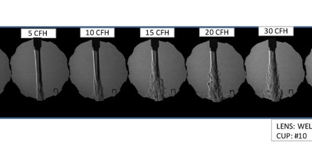
Not every TIG welding application has the same optimal gas flow rate. While gas flow rates for TIG welding are typically between 10 cfh and 35 cfh, the rate is impacted by the consumables being used and atmospheric conditions. First, be aware of how the shielding gas interacts with atmospheric gases. As the shielding gas exits the nozzle, its differing velocity and density compared to the atmospheric gases surrounding it can form currents. These currents can disrupt the desirable laminar flow of the shielding gas and cause turbulent flow. With more turbulence in the flow, atmospheric gases can be pulled into the shielding gas column, potentially contaminating the weld or tungsten electrode.
Increasing the gas flow rate increases the turbulence of the laminar flow column, which also increases the chance for contamination. While decreasing the flow rate reduces turbulence, keep in mind that a too-low flow rate can be easily disturbed, and it may not properly protect the weld or tungsten. It’s recommended to use the lowest gas flow rate possible while still achieving proper laminar flow for the application and conditions. For consistent flow rate accuracy and quick adjustments, place the flow meter regulator as close to the torch or welding power source as possible. Minimizing long shielding gas hoses reduces pressure that can build up in the supply line and cause high surges of gas on arc starts.
TIP NO. 4: USE GAS PRE- AND POST-FLOW WHEN NECESSARY
It can also be helpful to use pre-flow and post-flow gas coverage to help ensure optimal results in TIG welding. Prior to welding, a pre-flow of shielding gas of at least 0.2 seconds is recommended to help eliminate any initial surge of gas and to shield the tungsten electrode and weld area to better initiate the arc start. Post-flow helps assure the weld is protected as the weld pool solidifies and shields the electrode from atmospheric contamination as it cools after welding. For proper post-flow, hold the torch over the end of the weld until gas flow stops. Divide the welding amps being used by ten to determine the number of seconds needed to have a minimum post-flow for the shielding gas. A minimum of eight seconds is recommended, and 12 is my personal favorite. If you’re using long gas lines, be aware that the initial release of shielding gas upon starting the arc will be a much higher flow rate. To remedy this, use shorter gas lines or increase the gas pre-flow time to purge the lines and eliminate the surge of gas before starting the weld.
FOLLOW BEST PRACTICES
Proper consumable and gas choices coupled with key best practices can help you improve success in TIG welding. Remember that you want to choose options that deliver the best coverage. Achieving long laminar flow – and a larger gas envelope with the least amount of turbulence – reduce the risk of weld contamination.
Subscribe to learn the latest in manufacturing.


