How to Prevent Five Common Failures in Robotic Welding Systems
Are burnbacks, premature contact tip wear, loss of tool center point (TCP) or other problems costing your robotic welding operation time and money? Here are some tips that will improve productivity, reduce consumable costs and ensure consistent part quality in your robotic weld cell.
Posted: September 20, 2018
Is your robotic welding operation costing time and money for problems like burnbacks, premature contact tip wear, loss of tool center point (TCP) or other issues? These common failures in robotic welding can be costly, resulting in downtime and unplanned part replacement. Even issues that seem minor, such as the wire sticking to the contact tip and forcing tip replacement, can cost thousands of dollars per day when you consider lost consumables, cell downtime and labor costs for changeover. Beyond the time and money spent on minor issues, there’s also the risk of catastrophic failure that could short out the robot or damage system electronics, potentially costing tens of thousands of dollars. Avoiding common failures is often a matter of proper weld cell setup and robot maintenance, in addition to following some best practices for consumable installation. Operator training is also critical in preventing common failures in robotic welding.
FAILURE NO. 1: BURNBACK AND CONTACT TIP WEAR
One of the most common failures in a robotic weld cell is burnback and premature contact tip wear. The top cause of burnback is an improperly trimmed gun liner. When a liner is too short, it won’t seat in the retaining head properly, causing burnback. To avoid this problem, follow the manufacturer’s recommendations for proper liner trimming. It’s also helpful to choose a high quality liner designed for foolproof liner trimming and installation. Burnback is one cause of premature contact tip wear, but wear can also result from other factors. Using low quality wire with a lot of cast can be another cause, as it quickly wears out the contact tip compared to using a better quality, straighter wire. Drive rolls that are too tight can also cause wire cast issues that wear the contact tip faster. Improper welding parameters, such as welding too hot or too cold, can also wear contact tips prematurely and force more frequent changeout. Adjust parameters accordingly to minimize this problem.
FAILURE NO. 2: BROKEN CUTTER BLADES IN THE REAMER
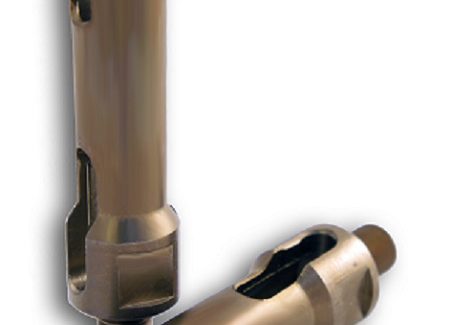
The main cause of broken cutter blades in robotic welding is incorrect positioning or too much angle of the robotic MIG gun nozzle as it enters the reamer for cleaning. For example, if the depth of the Z-axis is too deep, the torch will go in too far and may cause the reamer blades to break. To prevent this, the nozzle should be concentric to the cutting blade. Use an angle finder app on your smartphone or tablet to ensure the positioning is straight up and down on the X and Y positions. Also, be sure the insertion depth on the nozzle goes past the gas holes on the diffuser. Drag marks on the diffuser or contact tip are signs of wear that mean the nozzle is not concentric to the reamer blade. Proper setup and positioning also helps ensure consistent coverage of anti-spatter spray on the nozzle. Broken cutter blades can also result from excessive spatter in the nozzle, which can be caused by poor spraying setup, incorrect weld parameters or incorrect torch angle. Spatter sticks to spatter and as the buildup grows, it can break the cutter blade as it tries to enter the nozzle.
Keep in mind that you may need to ream and spray more frequently depending on the application and the material being welded to avoid some of these issues. Problems with the contact tip, nozzle, reamer and excessive spatter can also result when there is poor grounding in the weld cell. Regularly inspect all cables for damage and be sure the ground cables are securely connected.
FAILURE NO. 3: LOSS OF TOOL CENTER POINT
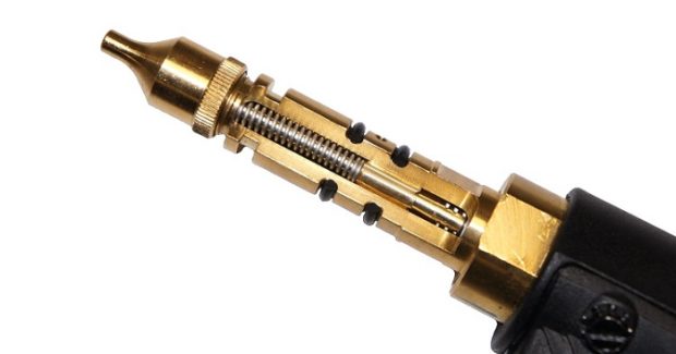
When TCP is lost in a robotic weld cell, one common cause is improperly installed consumables. A cross-threaded consumable will angle the contact tip where it meets the retaining head, causing the tip to bend and disrupting TCP. Be sure to tighten consumables to the manufacturer’s torque specifications. The general rule of thumb is one quarter turn past finger tight. A worn clutch can also cause loss of TCP. The clutch system helps prevent damage to the robot or gooseneck during tooling collisions. After repeated incidents, the clutch may allow a few degrees of movement in either direction, which throws off TCP. Consider using a neck inspection fixture, which tests and adjusts the tolerance of a robotic MIG gun’s neck to the TCP so that you can readjust it after an impact or after bending due to routine maintenance.
FAILURE NO. 4: BROKEN DISCS
In a robotic weld cell, the disc functions as a buffer between the mount and the robot arm. It’s designed to be sacrificial: if the torch, mount or robot arm collide, the disc will absorb the bulk of the impact. However, the disc can be broken when it’s hit hard enough by the gooseneck or torch mount, so replace it if damaged. Set the robot path correctly to avoid gooseneck collisions. Overtightening the screws can also break or crack the disc and cause it to fail. Discs have torque specifications from the manufacturer. Use those specifications to prevent overtightening and reduce the risk of cracking. The specification sheet also describes the order in which the screws on the disc should be tightened.
FAILURE NO. 5: INCORRECT TOOL PATH
Robotic weld cell failures can also be caused by programming errors. If the robot’s path to the tooling is programmed incorrectly, the arm can come into contact with the tooling or the weld cell wall. The torch rubbing on the cell wall can create holes in the cable. In addition, if the gooseneck frequently hits the tooling, this can bend the neck or cause the disc to break. To prevent these issues, program the robot so the arm is clear of the tooling and doesn’t encounter the tooling or the wall.
MAINTENANCE IS KEY
Preventive maintenance is key to keeping a robotic welding system and its components performing optimally – and extending consumable life. Regularly check all cables to make sure they are secure, free of damage and not rubbing anything. Establish and follow a schedule for liner changeover. The required frequency of liner changeover depends on what type of filler metal is being used, what material is being welded and shop conditions. A shop that is very dusty means liners will clog faster, for example. Consult the manufacturer’s maintenance recommendations and follow a preventive maintenance checklist to ensure all the system’s components and parts remain in good working order. Using high quality robotic MIG guns and consumables also helps prevent problems that can arise in the weld cell. Taking steps to avoid common failures in the robotic weld cell allows your operation to improve productivity, reduce consumable costs and ensure consistent part quality.


