Sheet Metal Marking Review
Demands are growing for sheet metal fabricators to mark their parts during production for product traceability in the field and better efficiencies in the shop, but many part identification systems can add an unnecessary secondary process. Whenever possible, consider finding ways to incorporate part marking into a manufacturing step that is already required. Here are some ways to use the equipment that you already have.
Posted: October 24, 2018
For a wide variety of reasons, more and more fabricators are introducing part marking into their sheet metal production processes. In some industries, the need for traceability in products and manufacturing processes have long dictated marking requirements. Others that haven’t traditionally had this requirement are now moving in the direction of higher traceability, driven by demands from customers, installers and service technicians to provide better identification and tracking of their products. Aside from product identification for end users and technicians, within the production process itself there are a lot of good reasons to incorporate marking on sheet metal parts: Material numbers and dot-matrix codes can help machine operators correctly identify parts that require processing, minimizing the chance of errors and waste. Marks that help welders locate and orient components in an assembly can reduce setup time and improve throughput. Assembly instructions marked directly onto parts can be a huge time saver when it comes to getting finished goods ready for shipment.
Because this topic comes up often in sheet metal production, it’s a good idea to periodically review the state-of-the-art in the industry. Lots of solutions exist specifically for part identification, from very sophisticated portable laser marking machines to very simple printed stick-on labels, and the requirements of a specific product or production method may dictate certain specialized marking applications. Still, anytime we can avoid discrete secondary processes we also avoid the additional handling effort, bottlenecks, and potential for mistakes that come with each manufacturing step. This means that if we can incorporate marking into a manufacturing step that is already required, it is worth considering. Most fabricators are aware that laser cutting and punching machines are capable of marking parts, but the range of possible marking options that is already available to you might be surprising.
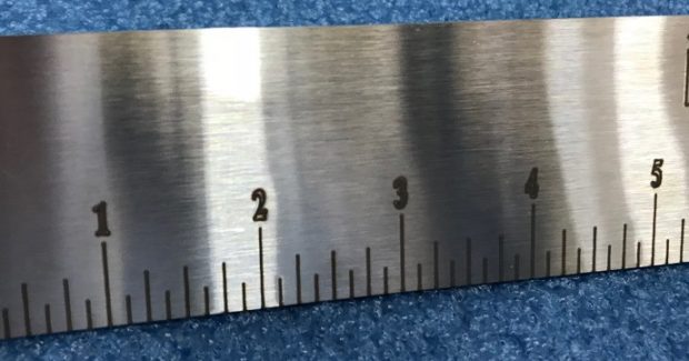
Laser cutting machines with both CO2 and solid-state sources are capable of dialing-down the power output to a level that is useful for etching and engraving. Two different methods that are based on the assist gas type are widely used: Laser etching with oxygen assist gas will generate a black mark on sheet metal, which is ideal for legibility, whereas nitrogen etching will produce a mark on most sheet metals that is silver in color. Etching with nitrogen tends to produce finer lines, but the legibility of the marks, especially on shiny materials like aluminum and stainless steel, may not be sufficient. Oxygen etching provides excellent contrast for marks on those shiny materials, but the marked lines might look a bit “fuzzy” compared to nitrogen etching.
In general, laser etching produces marks that are not very deep, which can be ideal if you want marks that will disappear under paint. But if you need marks that will last a long time on the end product or that will show through a coat of paint, many laser machines are also capable of “deep engraving” that usually entails feeding some specialized laser parameters into the equipment to create a mark that shows through paint or will hold up to wear conditions (frequent handling, for example). Contacting technical support for the manufacturer of your laser machine is the best way to find out if your machine can support a deep engraving technique.
With cutting machines powered by solid-state laser sources, some additional options can open up in the field of part identification. As mentioned above, dot matrix codes can be a very useful way of coding important information into a small area of a component. This may be used for traceability by the end customer – who doesn’t want to be able to scan a product and automatically be taken to the customer service website for its support? – or to help with properly identifying the part during production. A more common sight at press brakes these days are code scanners that are capable of reading dot matrix or bar codes off of a shop traveler: This helps the operator of the press brake load programs faster on the machine control and also eliminates the chance of confusing different part numbers, engineering revisions or other changes.
In addition to being able to make the fine, precise marks necessary for dot matrix codes, solid-state lasers are also capable of making extremely fine slits in thin sheet metal (typically up to around 1/8 in thick). Locating marks and text that are actually slit through the material have the advantage of holding up to any sort of wear the part might undergo and can also go through a deburring or finishing process without vanishing. Because of the small kerf size, high beam quality and optimal absorption rate of solid-state lasers, alphanumeric characters and symbols can be slit through the material with high quality. Flatbed lasers with CO2 sources will be more limited in this capacity; they can still slit-cut thin material, but due to the larger kerf and slower feed rates the quality of their cuts may not be acceptable.
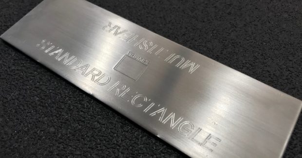
Punching machines, due to the possibilities that come with applying controlled pressure to a part, can provide many different methods for part identification. Obviously, punching machines can form alphanumeric text, symbols and even brand logos directly onto a metal part with embossing tools. This type of marking will show up through paint coatings and certainly has the advantage of long-term durability. These machines have also long been able to mark symbols and text using a dot-peening method. But did you know that many punching machines can also engrave? Several manufacturers have developed tooling systems that allow the mechanical scratching of sheet metal, which produces a very aesthetic mark comparable to the type of engraving you’d see at a mall curio store.
An even newer development is the introduction of “marker tools” which are punch tools that use an ink reservoir and felt tip to create marks in the same way as a felt-tipped pen. This technology allows shops to add detailed instructions for further manufacturing processes right at the punch machine that will disappear completely with a cloth and some acetone – a truly great thing if you are working with cosmetic stainless or aluminum parts that cannot have any permanent marks.
Of course, putting all of this together means that the ideal cutting and marking equipment would be a punch/laser combination machine that can provide any of the solutions covered here! Nonetheless, even if you don’t have the ideal marking system already sitting on your factory floor, the odds are very good that your present cutting equipment does have some marking functionality that could be useful. For many, the trick is in finding ways to incorporate part marking into the work you are already doing. The best way to start is by looking closely at the processes that follow cutting and see where better identification on the parts could save your team some time. A little investigation along these lines could lead to a surprising payoff in quality and productivity.


