Simulation Software Takes Guesswork Out of 3D Metal Printing
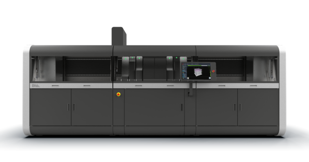
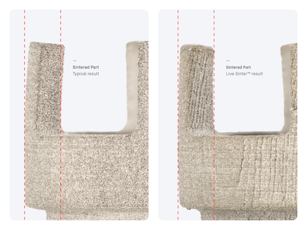
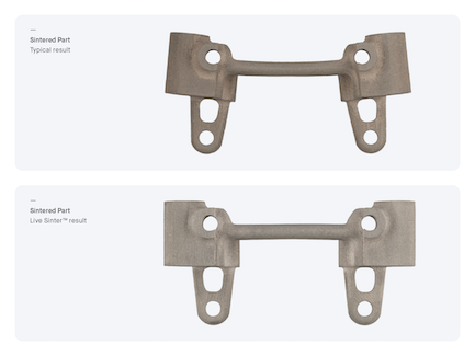
Live Sinter enables inexperienced 3D-printer operators to consistently produce accurate parts using Desktop Metal’s Shop System and Production System machines. The software automatically overcorrects for the shrinkage and distortion inherent in sintering.
Posted: December 3, 2020
Sintering is a critical step in powder metallurgy-based manufacturing processes such as binder jetting. It involves heating parts to near melting to impart strength and integrity, and typically causes them to shrink by as much as 20% from their printed or molded dimensions. During the process, improperly supported parts also face risk of deformation, resulting in parts that emerge from the furnace cracked, distorted, or requiring costly post-processing to achieve dimensional accuracy.
Manufacturers have coped with this reality by relying on industry veterans who, through repeated trial and error, combine adjustments to part designs with supports to enable stable, high-volume production. Live Sinter from Desktop Metal Inc. (Burlington, MA) delivers accurate parts without requiring users to be experts in powder metallurgy.
The simulation software predicts and automatically compensates for shrinkage and distortion, creating “negative offset” geometries that, once printed, will sinter to design specifications. The program runs on a graphics processing unit (GPU)-accelerated engine that models collisions and interactions between hundreds of thousands of connected particle masses and rigid bodies. The simulation is validated using meshless finite element analysis (FEA), which computes stress, strain, and displacement across part geometries. Compared to more general-purpose simulation tools that use complex meshes and require complex setups and hours to complete, this dual-technology approach strikes a balance between speed and accuracy.
In addition to correcting for shrinkage and distortion, the software opens the door to printing complex geometries. Improving part shape and dimensional tolerances improves the chances of first-time success and minimizes the cost and time associated with post-processing. In many cases, parts can be sintered without the use of supports.
The software can simulate a sintering cycle in five minutes and generate negative offset geometries that compensate for shrinkage and distortion in 20 minutes. It can be calibrated to a variety of alloys and sintering hardware and process parameters with minimal additional effort.
While compatible with any sintering-based powder metallurgy process including metal injection molding (MIM), the software is first available to buyers of the Shop System and Production System 3D printers.
Designed for machine shops, the Shop System is an affordable binder jetting machine that runs up to 10 times faster than legacy powder bed fusion technologies. The Production System uses the same low-cost powers used in metal injection molding (MIM) and is up to 100 faster than legacy technologies, enabling production quantities of millions of parts per year at costs competitive with conventional mass production techniques.


