Intelligent CAD/CAM Toolpaths Allow Tools to Cut Metal at Impressive Speeds
By implementing intelligent toolpath strategies, one company was able to reduce cycle time for one part from 40 minutes to 10-to-15 minutes by achieving a full depth of cut, increasing feeds and speeds, and normalizing the load on the tool. How low can you go with these solutions?
Posted: August 5, 2021
Depth of Cut
By Jesse Trinque
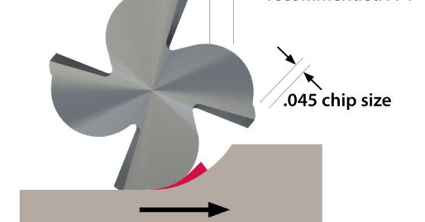
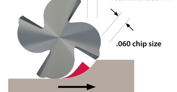
The world is abuzz with the wonders of additive manufacturing but there are noteworthy achievements taking place in the world of subtractive manufacturing as well. While material removal is not a new way of producing parts, innovations continue to be made that allow manufacturers to reduce time and costs while still turning out complex components. Radial Chip Thinning (RCT) is one of them. RCT has to do with the behavior of cutting tools when stepovers are 50 percent or less. As stepovers decrease, tool wear also decreases, even with the chip load remaining constant. In order to maintain the same chip load with a reduced stepover, feed rates can be drastically increased to maintain chip thickness and manage heat removal from the tool’s cutting edge. Heat can break down coatings and eventually cause the underlying carbide to fail prematurely. This, and a resulting larger depth of cut, is achievable when using a flexible, easy-to-use stock-aware CAD/CAM software program that is capable of applying the age-old concept of RCT to complex geometries.
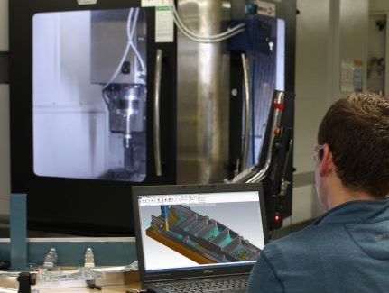
The preferred feed-per-tooth or cutting condition that the tool will be subject to is specified during programming. The programmer can essentially choose what is important to him or her. The software, using a proprietary algorithm, ensures the tool stays within those specified operating conditions — no matter the geometry. While it’s always been easy to achieve optimal cutting parameters on a straight cut while shouldering along the side of a block, historically, as soon as the corner appears, the tool tends to over engage, wandering outside the optimal cutting parameters. With non-adaptive cutting strategies, the forces on the tool can skyrocket, leading to increased tool wear and ultimately catastrophic failure. Intelligent toolpaths automatically optimize the path the tool is following by “seeing” areas of the part where the material needs to be removed, calculating far in advance how to avoid sharp corners and other complex geometries. The tool goes from a straight shouldering application to an adaptive peel mill-style tool motion, all while still maintaining the same optimal cutting parameters. The software continually accounts for lateral forces on the cutting tools throughout the entire roughing path by tracking and anticipating remaining stock. Chatter, vibration, and air cuts are significantly reduced, if not eliminated. This allows for an increase in material removal as stepovers and depth of cut (DOC) can be increased tremendously. With no worries of laterally overloading the tool, the entire length of the tool’s flutes can be dropped down into the part to remove even more volume of material per pass.
In a traditional machining approach, we have to keep that small DOC because we’re over-engaging the tool in different areas. You are stuck running at reduced efficiency for 95 percent of the part for a condition that is only present for less than 5 percent of the cut. With intelligent toolpaths, over-engagement does not occur, and optimal cutting parameters are constantly maintained, allowing us to maximize the depth of cut and really crank up our material removal rates for optimal efficiency. Shop rates for machine tools are not cheap and maximizing every hour of spindle run time is critical.
Adapting Strategies and Principles Benefits the Entire Process
It’s a given that faster feeds and speeds result in an increased force — pressure on the tool, workholding systems, and spindle — that accompanies removal of large amounts of material. Intelligent toolpaths remove the peaks and valleys of these loads, making for a more consistent set of forces on the entire machining process. But, as material removal rates increase, it’s still important for the tool to be held firmly. When the limits of a given tool are pushed, holder options like safe locks or hydraulic minimize tool pull out. Likewise, cheap commodity-type vices will not do. It’s important to note, however, that high torque, high horsepower spindles are not necessarily essential to utilize these principles or technology when material is to be removed at less than 50 percent stepovers and deeper stepdowns. Remember, these toolpaths are all about consistency and some machines aren’t capable of running at super high speeds. Getting the machining process into an optimal range, whatever that may be, is most important and these strategies do allow for massive benefit even at more conservative feeds and speeds.
It’s also worth noting that many shops design their own fixtures. Leveraging a capable CAM system and applying the principles mentioned above allows for quick turnaround on these tasks that are often considered overhead. These intelligent toolpaths also shave significant time off of machining workholding fixtures tailored to individual projects. The benefits of adapting these principles and strategies can be felt throughout the entire manufacturing process.
Intelligent Toolpath Solutions and the Real World
It’s good to talk in theory about how intelligent toolpaths achieve optimal cutting parameters and thus allowing more depth of cut, but it’s equally important to demonstrate real world results.
One of our customers was machining 2D components made from Hastelloy-X, an extremely hard and difficult-to-machine material, using a traditional machining strategy involving shallow depths of cut but a large stepover. Cycle time on one part was around 40 minutes. The company threw away one end mill with every part produced and, in some cases, couldn’t get through machining the entire part without changing the end mill mid-cycle and then finish cleaning up the part. The low DOC resulted in a tool with the bottom one hundred thousandths of the flutes chipped, even running painfully slow speeds and feeds with traditional programming methods. When we implemented our toolpath strategies, we were able to reduce cycle time for one part down to 10-to-15 minutes by achieving a full depth of cut, increasing feeds and speeds, normalizing the load on the tool, and producing nearly seven parts using one end mill.
Another customer, Stewart Haas Racing (Kannapolis, N.C.), is involved with producing components for the car chassis, body and engine for its NASCAR team. The company’s manufacturing center supports three NASCAR teams and there are three engineering groups designing parts for these cars. The company experienced trouble producing a complex spindle component. This component is the cornerstone of the entire front suspension. It’s a very intricate piece made out of a high-strength steel. It took the manufacturing center days to machine all of the 3D operations to rough out the part, and then a few more days for finishing. There were many broken tools and time spent chasing areas of tool over engagement and other various programming issues. We recommended a 3D toolpath strategy that first roughs at a full depth of cut and then steps the tool up along the 3D surfaces to create a 3D shape. This utilizes the same 2D toolpath technology explained earlier. This is a feature-based machining strategy allowing for full roughing from programmer specified planes on a 5-axis machine. Implementation resulted in tool life and programming efficiency going way up.
In other cases, we’ve seen parts that previously took 25 2D operations reduced to one using this toolpath technology.
It’s easy to see how these adaptive toolpathing strategies allow the entire flute length of the tool to be used, but tool considerations play a big part in achieving optimal success. There is one school of thought that says, “I’m not paying this much for a tool to rough a part out when I can buy the same thing online at a discount.” The other school of thought says, “If I can push this higher end tool four times as hard and it lasts four times as long in-cut, the tool cost is actually less.” It’s an important thing to consider when moving to larger production runs. In many cases, the tools being used already have a longer flute length than what is normally used. Running deeper cuts, a longer tool makes more sense as all of that carbide will be used before the tool is scrapped.
The ability to program intelligent toolpaths that drive the tool in the easiest to machine materials like aluminum, through the hardest Hastelloy-Xs of the world, is a game changer for metal fabricators who need to cut parts efficiently but prefer to avoid the high costs of premature tool degradation. By using the entire length of the flute with little to no vibration, chatter, or other adverse conditions, fabricators can machine more parts with fewer tools and achieve depths of cut never before imaginable to rough out deeper blocks of material in less time. How low can you go?


