What Is Weld Tensile Testing and Why Is It Important?
Tensile testing helps ensure that a weld meets the required levels of strength and ductility.
Posted: September 14, 2021
WELDING TIPS
By Robert Fox
Filler metal manufacturers perform tensile testing on many of their products for several reasons. Like many end users, they may perform tensile testing to help monitor process quality. Tensile testing is also used by these manufacturers to determine and maintain product classifications and approvals from agencies such as the American Welding Society (AWS) or the American Bureau of Shipping. The results of tensile testing are typically made available on filler metal data sheets and these values are critical in determining if a product is suitable for an application.
End users can also perform or outsource their own tensile testing. When companies need to follow welding codes, for such applications as structural or pressure vessel fabrication, tensile strength testing is often a critical component of the procedure qualification record that accompanies welding procedures. Even in applications that aren’t being welded to code, companies frequently conduct tensile testing to assess if the welds being produced are capable of providing sufficient strength for a particular application.
What is Tensile Strength Testing?
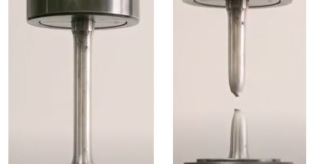
Tensile testing is a destructive testing method that is done early when testing weld performance. This easy-to-perform assessment provides a wealth of information that is critical for selecting the best filler metal for an application.
A sample of specified dimensions is loaded in tension until the point of failure. The sample piece is pulled apart to understand the strength, ductility and other characteristics of the weld. The test equipment calculates and displays the ultimate tensile strength [the maximum stress withstood before failure in pounds per square inch (psi) or megapascals (MPa), the yield strength (the stress where plastic deformation occurs in psi or MPa) and the percent elongation of the sample.
The process involves creating a welded test plate, machining the plate to produce an appropriately sized test specimen, conducting the test and then analyzing results. Different base metals, joint designs and welding parameters can result in significantly different mechanical properties, even when using the same filler metal. For this reason, filler metal manufacturers and companies test plates in accordance with specifications that control all of these factors.
Common Types of Tensile Tests
The three most commonly used types of tensile tests are:
- All weld metal testing — This involves testing only the weld metal of a sample welded test plate. It’s a standard test for filler metals and in some procedure qualification processes. Note that all weld metal tensile bars may contain areas of the weld where dilution with the base metal has occurred; it may not be possible on all weld joint configurations.
- Transverse tensile testing — In this process, a tensile bar is extracted from the transverse axis of the plate (perpendicular to the axis of the weld). As a result, both the weld metal and base metal are tested, capturing the interaction between the two. It’s a litmus test: It’s definitive that the weld metal is stronger than the base metal if the failure occurs in the base metal and vice versa. However, there are limitations to this type of testing. It is possible to extract ultimate tensile strength but not the yield strength or percent elongation (a measure of ductility) with a high degree of accuracy.
- Longitudinal tensile testing — This sample configuration involves testing a specimen that is extracted in the longitudinal axis of the weld. Depending on the joint design, a longitudinal tensile bar may contain both base metal and weld metal.
The code being followed governs the type of tensile testing required for a specific application. For example, welds for seismic applications typically have stricter tensile testing requirements (additional sample requirements) than an average weld made under AWS D1.1/D1.1M: Structural Welding Code – Steel. It’s important to always check code requirements before doing any type of tensile testing to ensure compliance.
Yield-Strength-Based Weldment Design
For many applications, the “advertised” or rated load-carrying capacity of a weldment is based on the ultimate tensile strength of the weld metal, less a factor of safety (often three to four times less).
However, some parts are designed based on yield strength, which is used when the part cannot permanently change dimensions. An example of these are machinery components or oil and gas transmission pipeline components. Parts designed with yield strength as a key focus will not typically reach the point where parts permanently deform, which may prohibit the part from performing as intended.
When designing based on yield strength, consider doing a tensile test that provides the yield strength number. An all-weld metal test will give you more complete information about the part than a transverse tensile test.
Less Common Testing Situations
Sometimes operations need to learn more about a filler metal than is indicated in a product data sheet. A good example is when post-weld heat treatment is required and the filler metal tensile strength has not been indicated by the filler metal specification or by the manufacturer.
- A rule of thumb with post-weld heat treatment is to heat treat the metal for one hour per inch of base material thickness. Typically, the longer heat is applied and the higher temperature used, the more the part’s tensile and yield strength will decrease (note that stress relief typically improves weld ductility). Therefore, it’s important to determine how long and at what temperature the stress relief will be performed and then perform procedure-qualification tensile testing at that time and temperature.
Another less common situation requiring special testing is elevated temperature tensile pulls, which are done to analyze creep strength of a material. This is more often done with high chromium-molybdenum (chromoly) steel alloys used for pressure vessels, power generation and high-temperature applications. This method requires the tensile sample to be heated to a specific temperature before it’s pulled apart.
When Testing Yields Different Values
There may be situations when an operation’s tensile testing results are significantly different from the filler metal manufacturer’s reported values. This is not always a cause for concern. Rather, it is a common occurrence due to differences in joint design and welding parameters between the requirements of the filler metal specification and the application itself.
This reinforces how important it is for users to conduct their own testing. The manufacturer’s tensile test data is performed using conditions required for AWS classification. As such, it is simply a starting point for determining a filler metal’s suitability for a particular application because filler metals will perform differently as operators change variables.
Situations where tensile test results can vary from the manufacturer’s reported data include:
- High-dilution welds — When the weld metal mixes with a large amount of base material — which happens frequently on very thin materials and with very narrow joint designs — it’s considered a high-dilution weld. An example of this is a two-pass groove weld on a butt joint using submerged arc welding, which is a high-dilution and high-heat input process. Different processes have different dilution rates, meaning different processes may exhibit different tensile strengths even though similar weld sizes are produced using similar joint geometry. A weld with low dilution will have test results more closely aligned with the filler metal manufacturer’s testing because they test undiluted weld metal. A high-dilution weld may have a lower tensile strength because filler metals are typically selected to provide a higher tensile strength (a slight overmatch) compared to the base metals. For example, consider ASTM A36 base material. Its tensile strength is often much lower (~50 ksi) than the 60- or 70-ksi tensile strength filler metals that are typically utilized with this material.
- High– and low–heat input welds — Be aware of the impact that heat input has on tensile strength. Higher heat inputs typically produce lower tensile strengths and lower heat inputs produce higher tensile strengths. Filler metal manufacturers typically test using a heat input between 35 and 60 kJ/in. If an operation wants to use a filler metal outside of that window — perhaps they want to use a higher heat input (caused by increased amperage/wire feed speed) to increase deposition rates — they often need to do their own tensile testing or collaborate with the filler metal manufacturer.
Understanding Weld Strength
Tensile testing is a crucial step in understanding weld performance and ensuring that a finished weld is as strong or stronger than the base metal. When welding to code, the requirements will include specifics about tensile testing, but even operations that aren’t welding to code can benefit from this testing data to guide cost-effective and safe part design.
Subscribe to learn the latest in manufacturing.


