How To Tell the Difference Between Solidification Lines and Cracks in Welding
Understand what causes solidification lines to save your shop unnecessary stress and costs.
Posted: January 3, 2022
WELDING TIPS
By Robert Fox
Weld cracking almost always occurs unexpectedly, but it can quickly become a major cause for concern when it does happen.
The discovery of weld cracking often demands the prompt coordination of operators and technicians, production management and welding engineers to develop a quick and effective resolution. Plus, the cost of rework or scrapped parts due to weld cracking has a significant impact on the bottom line.
However, another occurrence called solidification lines may generate unnecessary stress for welding operations if these lines are confused with weld cracking. Solidification lines share a similar appearance to hairline weld centerline cracks, but solidification lines are harmless and do not indicate a problem with weld quality.
To avoid unnecessary stress or downtime, it’s important to understand the causes of solidification lines and how to determine the difference from costly weld cracking.
WHAT DO SOLIDIFICATION LINES LOOK LIKE?
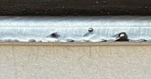
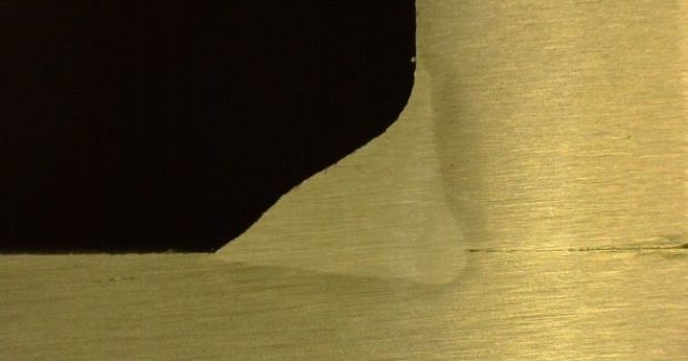
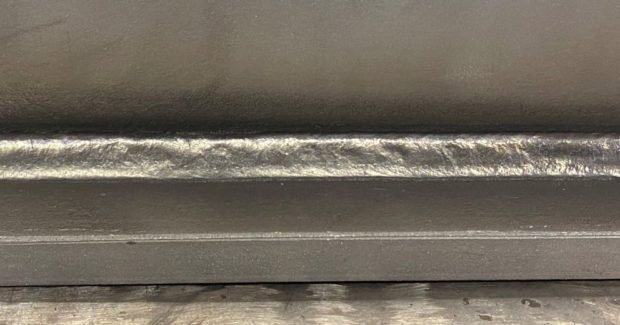
Solidification lines are depressions of miniscule depth that occur longitudinally along the weld centerline, typically present the entire length of the weld — from initiation to crater.
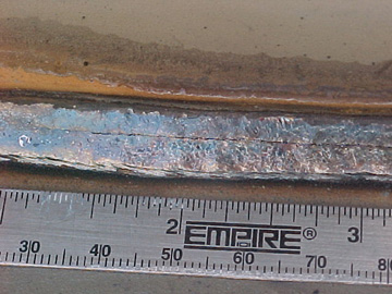
These lines are often mistaken for weld cracks, which can also manifest themselves longitudinally. Depending on several factors, weld cracks can be very fine and straight (similar to how many solidification lines look), though the conditions necessary to create such fine and straight cracks are a less common occurrence.
The presence of a solidification line does not necessarily indicate the presence of a crack, defect or discontinuity.
WHAT CAUSES AND PREVENTS SOLIDIFICATION LINES?
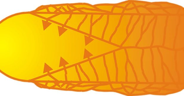
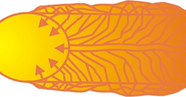
A weld cools from the edge toward the centerline, so the longitudinal axis is the last part to solidify. Grains continue to grow and form intersections (and sometimes vertical lines) until they meet in the weld centerline. This basic concept, combined with other factors, contributes to common causes of solidification lines.
- Weld-pool shape: This is typically the most frequent cause of solidification lines. During welding, the weld pool can be described as having an elliptical to teardrop shape that is influenced by travel speed and other welding parameters. High heat inputs (high amperage with high travel speed) will produce a more elongated, teardrop shape. If the teardrop shape becomes very narrow at the trailing end of the weld pool, a solidification line is more likely to occur. Lower heat inputs (low amperage with low to moderate travel speed) or high heat inputs that utilize low travel speed will produce weld pools that are more circular or elliptical in shape, with less of a teardrop tail (for less of a chance of solidification lines).
- Technique: Operator technique can also influence solidification lines. Oscillation often affects weld pool surface tension and may prevent the formation of a solidification line.
- Welding process: Certain processes are more likely to exhibit solidification lines. In flux-cored arc welding (FCAW), solidification is slower due to the slag coverage and lower travel speed compared to gas metal arc welding (GMAW), especially GMAW welds made using metal-cored wire. GMAW lacks slag coverage and has higher deposition rates than FCAW or shielded metal arc welding (SMAW). The lack of slag coverage has a noticeable effect on the weld cooling rate, although welds made using GMAW are more likely to exhibit solidification lines due to the higher travel speeds, which intensify a faster cooling rate. Welds made using solid wire or metal-cored wire can exhibit solidification lines. If it seems that metal-cored wires exhibit solidification lines more frequently, remember the differences between the wires that can contribute to the shape of the weld pool. The higher deposition rates of metal-cored wire compared to solid wire facilitate higher travel speeds, which is the largest contributor to heat input and, as a result, weld-pool shape. The increased puddle fluidity may facilitate the elimination or reduction of oscillation to ensure good weld-toe fusion. Plus, the comparatively stagnant weld pool would therefore be more likely to exhibit solidification lines.
- Base metal: Solidification lines don’t typically occur on aluminum base material. Solidification lines are most commonly observed on steel base metals when mill scale or other contaminants have been removed from the welding area. On steel materials with mill scale, the lines often present themselves differently. Mill scale can influence the weld surface tension and make it more likely for the weld to have more convexity. This results in a lower chance of solidification line formation.
WHAT DO WELD CRACKS LOOK LIKE?
If the factors that influence weld cracking combine to a high enough magnitude, the spread of the cracking can be rapid, and the weld metal will be unable to prevent it.
In some cases, the crack path will be very straight. Though less likely, these are the occurrences that can look similar to solidification lines.
With a lower level of contributing factors or improved weld ductility, the crack path may become more jagged. This more obvious zigzag crack shape is referred to as torturous propagation.
Weld hot cracking occurs at high temperatures — generally more than 1,000 degrees Fahrenheit (538 degrees Celsius) — and the defect appears more or less immediately (though not always visibly) upon solidification of the weld.
HOW DO YOU TELL THE DIFFERENCE BETWEEN WELD CRACKS AND SOLIDIFICATION LINES?
If an operation suspects they have weld cracking, there are several types of non-destructive and destructive test methods that can be used to determine if cracking has occurred. These tests can also confirm if what they are seeing are simply solidification lines rather than weld cracks.
Common non-destructive test methods include:
- Dye penetrant testing: This is one of the quickest and easiest non-destructive test methods. It can be performed on production parts in a matter of minutes. An operator applies a low viscosity penetrant to the workpiece, gives it time to penetrate, then wipes the workpiece clean and applies a developer solution. Cracks are indicated if the penetrant is visible through the developer. An ultraviolet-reactive penetrant can be used to better identify very small or fine cracks.
- Magnetic particle testing: This is also a quick testing option that takes relatively little time, equipment or skill to perform. A magnetic field is induced in a weldment using an electromagnetic current generator. A specialized dry magnetic powder or a fine magnetic particle suspended in a liquid carrier is then applied to the component. These powders and particles are attracted to defects, such as cracks, due to the changes in magnetic flux lines in areas where defects are present.
- Ultrasound testing: This is a good option if it is also implemented elsewhere in production, although this method typically requires a well-trained interpreter and can be more time consuming.
- Radiography: This test can also be time consuming and fine cracks may be difficult to detect depending on the position of the source of radiation relative to the workpiece. Trained personnel are also required for interpretation and to ensure the test is performed safely.
There are also destructive test methods available that can be used to identify weld cracks. Macrographs of the weld cross-section are one destructive test option that is typically done at the time of procedure qualification.
Oftentimes, developing a welding procedure is beneficial to the production welding environment, as it may allow identification of the risk at which welding defects or discontinuities may occur before implementation into production. As a result, fabricators and manufacturers are given an opportunity to determine if the lines present on a weld are harmless or more likely to be actual weld cracks.
SOLIDIFICATION LINES VS. WELD CRACKS
Depending on the welding process and filler metal being used, solidification lines are a natural part of weld cooling. When testing proves the occurrence is not a weld crack, it’s likely a harmless solidification line. Understanding what causes solidification lines — and what sets them apart from costly weld cracks — can help operations avoid unnecessary stress and costs.
Subscribe to learn the latest in manufacturing.

